Toyota Yaris: G16e-gts (engine Control) / Crankshaft Position Sensor
Components
COMPONENTS
ILLUSTRATION
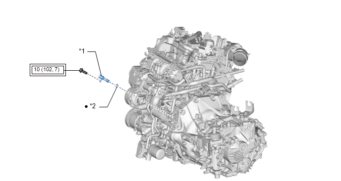
| *1 | CRANKSHAFT POSITION SENSOR | *2 | O-RING |
 | Tightening torque for "Major areas involving basic vehicle performance such as moving/turning/stopping" : N*m (kgf*cm, ft.*lbf) | ● | Non-reusable part |
Removal
REMOVAL
PROCEDURE
1. REMOVE STARTER ASSEMBLY
Click here

2. REMOVE CRANKSHAFT POSITION SENSOR
| (a) Disconnect the crankshaft position sensor connector. |
|

(b) Remove the bolt and crankshaft position sensor from the cylinder block sub-assembly.
NOTICE:
If the crankshaft position sensor has been struck or dropped, replace it.
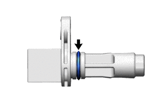
| (c) Remove the O-ring from the crankshaft position sensor. NOTICE:
|
|
Installation
INSTALLATION
PROCEDURE
1. INSTALL CRANKSHAFT POSITION SENSOR
| (a) Clean the O-ring groove of the crankshaft position sensor. NOTICE: Make sure the O-ring groove is free of foreign matter. |
|

(b) Install a new O-ring to the crankshaft position sensor.
NOTICE:
Set the O-ring on the tip of the crankshaft position sensor and roll it into the O-ring groove with bare hands to install it.
(c) Check if the O-ring is twisted.
| (d) Install the crankshaft position sensor to the cylinder block sub-assembly with the bolt. Torque: 10 N·m {102 kgf·cm, 7 ft·lbf} NOTICE:
|
|
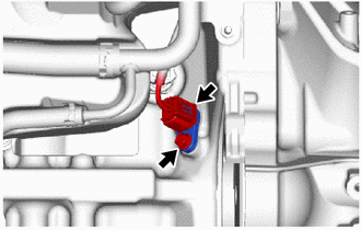
(e) Connect the crankshaft position sensor connector.
2. INSTALL STARTER ASSEMBLY
Click here

3. INSPECT FOR ENGINE OIL LEAK
Click here

 Installation
INSTALLATION PROCEDURE 1. INSTALL CAMSHAFT POSITION SENSOR (for Intake Side) (a) Clean the O-ring groove of the camshaft position sensor. NOTICE: Make sure the O-ring groove is free of foreign matter...
 Ecm
Ecm
..
Other information:
Toyota Yaris XP210 (2020-2026) Reapir and Service Manual: System Diagram
SYSTEM DIAGRAM Communication Table Transmitting ECU / Parts (Transmitter) Receiving ECU / Parts (Receiver) Signal Communication Method Front Airbag Sensor Airbag Sensor Assembly Front collision G signal Direct line No...
Toyota Yaris XP210 (2020-2026) Reapir and Service Manual: Precaution
PRECAUTION NOTICE: If the auxiliary battery has been discharged and charged or the cable has been disconnected and reconnected to the negative (-) auxiliary battery terminal, perform Steering Sensor Zero Point Calibration. Click here PRECAUTION FOR DISCONNECTING CABLE FROM NEGATIVE AUXILIARY BATTERY TERMINAL PRECAUTIONS FOR LANE TRACING ASSIST SYSTEM (a) Precautions for Using the Lane Tracing Assist System (1) The lane tracing assist system provides information to the driver and performs steering assistance according to the road and driving conditions...
Categories
- Manuals Home
- Toyota Yaris Owners Manual
- Toyota Yaris Service Manual
- Engine Start Function When Key Battery is Dead
- G16e-gts (engine Mechanical)
- Immobilizer System
- New on site
- Most important about car
Keys

To use the auxiliary key, press the knob and pull out the auxiliary key from the smart key.
