Toyota Yaris: Camshaft Position Sensor / Removal
REMOVAL
PROCEDURE
1. SEPARATE ENGINE WIRE
| (a) Remove the bolt and engine wire. |
|
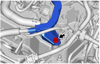
2. REMOVE IGNITION COIL ASSEMBLY
| (a) Disconnect the ignition coil assembly connector. |
|
(b) Remove the bolt and ignition coil assembly.
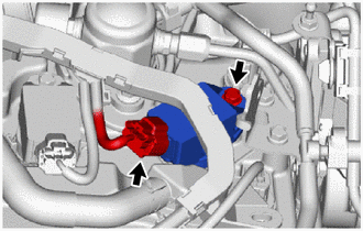
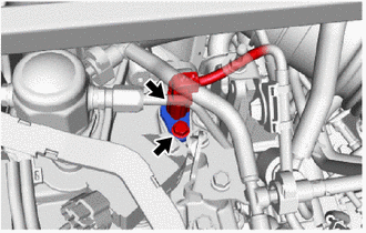
3. REMOVE CAMSHAFT POSITION SENSOR (for Intake Side)
| (a) Disconnect the camshaft position sensor connector. |
|
(b) Remove the bolt and camshaft position sensor from the cylinder head cover sub-assembly.
NOTICE:
If the camshaft position sensor has been struck or dropped, replace it.
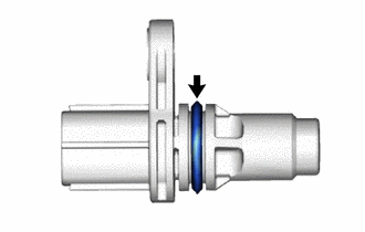
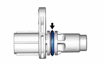
| (c) Remove the O-ring from the camshaft position sensor. NOTICE:
|
|
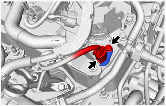
4. REMOVE CAMSHAFT POSITION SENSOR (for Exhaust Side)
| (a) Disconnect the camshaft position sensor connector. |
|
(b) Remove the bolt and camshaft position sensor from the cylinder head cover sub-assembly.
NOTICE:
If the camshaft position sensor has been struck or dropped, replace it.
| (c) Remove the O-ring from the camshaft position sensor. NOTICE:
|
|
 Components
COMPONENTS ILLUSTRATION
*A for Intake Side *B for Exhaust Side *1 CAMSHAFT POSITION SENSOR *2 IGNITION COIL ASSEMBLY *3 ENGINE WIRE *4 O-RING
Tightening torque for "Major areas involving basic vehicle performance such as moving/turning/stopping" : N*m (kgf*cm, ft...
 Installation
INSTALLATION PROCEDURE 1. INSTALL CAMSHAFT POSITION SENSOR (for Intake Side) (a) Clean the O-ring groove of the camshaft position sensor. NOTICE: Make sure the O-ring groove is free of foreign matter...
Other information:
Toyota Yaris XP210 (2020-2026) Reapir and Service Manual: Freeze Frame Data
FREEZE FRAME DATA DESCRIPTION The engine stop and start ECU records vehicle and driving condition information as freeze frame data the moment a DTC is stored. When troubleshooting, freeze frame data can be helpful in determining whether the vehicle was moving or stationary, whether the engine was warmed up or not, as well as other data recorded at the time of a malfunction...
Toyota Yaris XP210 (2020-2026) Reapir and Service Manual: 4WD Control ECU Communication Stop Mode
DESCRIPTION Detection Item Symptom Trouble Area 4WD Control ECU Communication Stop Mode Communication stop for "Four Wheel Drive Control" is indicated on the "Communication Bus Check" screen of the GTS. Click here 4WD ECU assembly branch line or connector Power source circuit of 4WD ECU assembly 4WD ECU assembly ground circuit 4WD ECU assembly WIRING DIAGRAM CAUTION / NOTICE / HINT CAUTION: When performing the confirmation driving pattern, obey all speed limits and traffic laws...
Categories
- Manuals Home
- Toyota Yaris Owners Manual
- Toyota Yaris Service Manual
- Auto Lock/Unlock Function
- Removal
- Battery Monitor Module General Electrical Failure (P058A01)
- New on site
- Most important about car
Turning the Engine Off
Stop the vehicle completely. Manual transaxle: Shift into neutral and set the parking brake.Automatic transaxle: Shift the selector lever to the P position and set the parking brake.
Press the push button start to turn off the engine. The ignition position is off.