Toyota Yaris: Wiper Switch / Inspection
INSPECTION
PROCEDURE
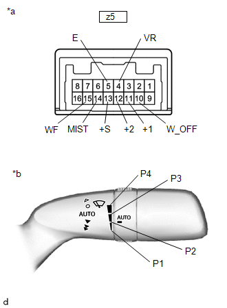
1. INSPECT WINDSHIELD WIPER SWITCH ASSEMBLY
(a) Check the resistance.
| (1) Measure the resistance according to the value(s) in the table below. Standard Resistance: Front Wiper Switch
If the result is not as specified, replace the windshield wiper switch assembly. |
|
 Removal
REMOVAL PROCEDURE 1. REMOVE LOWER STEERING COLUMN COVER NOTICE: Removing the lower steering column cover in the incorrect order will cause the parts to break...
 Installation
INSTALLATION PROCEDURE 1. INSTALL WINDSHIELD WIPER SWITCH ASSEMBLY (a) Turn the steering wheel assembly to the right. (b) Engage the claw to install the windshield wiper switch assembly as shown in the illustration...
Other information:
Toyota Yaris XP210 (2020-2026) Reapir and Service Manual: Accelerator Pedal
ComponentsCOMPONENTS ILLUSTRATION *1 ACCELERATOR PEDAL SENSOR ASSEMBLY *2 NO. 1 INSTRUMENT PANEL UNDER COVER SUB-ASSEMBLY Tightening torque for "Major areas involving basic vehicle performance such as moving/turning/stopping" : N*m (kgf*cm, ft...
Toyota Yaris XP210 (2020-2026) Reapir and Service Manual: Vehicle Control History
VEHICLE CONTROL HISTORY NOTICE: When checking the vehicle control history, first record the output codes and after clearing the history, check the output history again. CHECK VEHICLE CONTROL HISTORY (LANE TRACING ASSIST SYSTEM) (a) According to the display on the GTS, check the vehicle control history...
Categories
- Manuals Home
- Toyota Yaris Owners Manual
- Toyota Yaris Service Manual
- Power Integration No.1 System Missing Message (B235287,B235587,B235787-B235987)
- Adjustment
- Fuel Gauge
- New on site
- Most important about car
Front Seat Belt Pretensioners
The front seat belt pretensioners are designed to deploy in moderate or severe frontal, near frontal collisions.
In addition, the pretensioners operate when a side collision or a rollover accident is detected. The pretensioners operate differently depending on what types of air bags are equipped. For more details about the seat belt pretensioner operation, refer to the SRS Air Bag Deployment Criteria.