Toyota Yaris: Air Fuel Ratio Sensor (for Sensor 2) / Installation
INSTALLATION
PROCEDURE
1. INSTALL NO. 2 AIR FUEL RATIO SENSOR
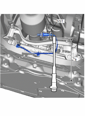
| (a) Using SST, install the No. 2 air fuel ratio sensor to the front exhaust pipe assembly. SST: 09224-00012 Torque: Specified tightening torque : 44 N·m {449 kgf·cm, 32 ft·lbf} NOTICE: If the No. 2 air fuel ratio sensor has been struck or dropped, replace it. HINT:
|
|

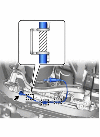
| (b) Engage the 3 wire harness clamps. NOTICE: Make sure the white tube is between the wires. |
|
(c) Connect the No. 2 air fuel ratio sensor connector.
2. INSTALL CENTER NO. 1 FLOOR BRACE
Click here

3. INSTALL CENTER FRONT FLOOR BRACE
Click here

4. INSTALL CENTER NO. 4 ENGINE UNDER COVER
Click here

5. INSPECT FOR EXHAUST GAS LEAK
Click here

6. PERFORM INITIALIZATION
(a) Perform "Inspection After Repair" after replacing the No. 2 air fuel ratio sensor.
Click here

 Inspection
INSPECTION PROCEDURE 1. INSPECT NO. 2 AIR FUEL RATIO SENSOR (a) Measure the resistance according to the value(s) in the table below. Standard Resistance: Tester Connection Condition Specified Condition D109-1(HA1B) - D109-2(+B) 20°C (68°F) 1...

Other information:
Toyota Yaris XP210 (2020-2026) Reapir and Service Manual: Removal
REMOVAL CAUTION / NOTICE / HINT HINT: When removing the name plates, heat the vehicle body, back door outside garnish and name plates using a heat light. Heating Temperature Item Temperature Vehicle Body Back Door Panel 40 to 60°C (104 to 140°F) Back Door Outside Garnish Name Plates 20 to 30°C (68 to 86°F) CAUTION: Do not touch the heat light and heated parts, touching the heat light may result in burns...
Toyota Yaris XP210 (2020-2026) Reapir and Service Manual: Problem Symptoms Table
PROBLEM SYMPTOMS TABLE HINT: Use the table below to help determine the cause of problem symptoms. If multiple suspected areas are listed, the potential causes of the symptoms are listed in order of probability in the "Suspected Area" column of the table...
Categories
- Manuals Home
- Toyota Yaris Owners Manual
- Toyota Yaris Service Manual
- Maintenance
- Adjustment
- Auto Lock/Unlock Function
- New on site
- Most important about car
Supplemental Restraint System (SRS) Precautions
The front and side supplemental restraint systems (SRS) include different types of air bags. Please verify the different types of air bags which are equipped on your vehicle by locating the “SRS AIRBAG” location indicators. These indicators are visible in the area where the air bags are installed.
The air bags are installed in the following locations:
The steering wheel hub (driver air bag) The front passenger dashboard (front passenger air bag) The outboard sides of the front seatbacks (side air bags) The front and rear window pillars, and the roof edge along both sides (curtain air bags)