Toyota Yaris: Canister / Inspection
INSPECTION
PROCEDURE
1. CHECK CANISTER (FUEL SUCTION WITH PUMP AND GAUGE TUBE ASSEMBLY)
(a) Visually check the canister (fuel suction with pump and gauge tube assembly).
(1) Visually check the canister (fuel suction with pump and gauge tube assembly) for cracks or damage.
If cracks or damage are found, replace the canister (fuel suction with pump and gauge tube assembly).
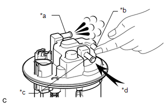
(b) Inspect the airflow of the canister (fuel suction with pump and gauge tube assembly).
| (1) Close the port (B) and check that air flows from the port (A) when air is blown into the port (C). OK: Air flows from the port (A). |
|
(c) Inspect the check valve.
| (1) Close the port (C) and check that air flows from the port (B) when air is blown into the port (A). OK: Air flows from the port (B). |
|
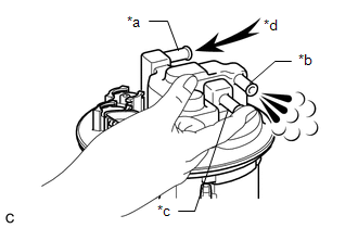
| (2) Using a vacuum pump, apply vacuum to the port (A) with the port (C) closed and check that air flows into the port (B). OK: The vacuum is maintained at first. By gradually increasing the vacuum, air flows and the vacuum decreases after the vacuum reaches a certain level. |
|

 Removal
REMOVAL CAUTION / NOTICE / HINT The necessary procedures (adjustment, calibration, initialization or registration) that must be performed after parts are removed and installed, or replaced during canister (fuel suction plate sub-assembly) removal/installation are shown below...
 Installation
INSTALLATION PROCEDURE 1. INSTALL FUEL MAIN VALVE ASSEMBLY Click here
2. INSTALL FUEL PUMP Click here
3. INSTALL FUEL SENDER GAUGE ASSEMBLY Click here
4...
Other information:
Toyota Yaris XP210 (2020-2026) Reapir and Service Manual: Data List / Active Test
DATA LIST / ACTIVE TEST DATA LIST HINT: Using the GTS to read the Data List allows the values or states of switches, sensors, actuators and other items to be read without removing any parts. This non-intrusive inspection can be very useful because intermittent conditions or signals may be discovered before parts or wiring is disturbed...
Toyota Yaris XP210 (2020-2026) Reapir and Service Manual: Components
C..
Categories
- Manuals Home
- Toyota Yaris Owners Manual
- Toyota Yaris Service Manual
- Maintenance
- Fuse Panel Description
- Brake System Control Module "A" System Voltage System Voltage Low (C137BA2)
- New on site
- Most important about car
Fuel Gauge
The fuel gauge shows approximately how much fuel is remaining in the tank when the ignition is switched ON. We recommend keeping the tank over 1/4 full.
