Toyota Yaris: Seat Heater Switch / Inspection
INSPECTION
PROCEDURE
1. INSPECT SEAT HEATER SWITCH (for LH Side)
| (a) Check the resistance. (1) Measure the resistance according to the value(s) in the table below. Standard Resistance:
|
| ||||||||||||||||||||||
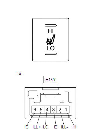
(b) Check the indicator illuminates.
(1) Apply battery voltage to the seat heater switch and check that the seat heater switch indicator illuminates.
OK:| Measurement Connection | Switch Condition | Specified Condition |
|---|---|---|
| If the result is not as specified, replace the seat heater switch. | ||
| Battery positive (+) → H135-6 (IG) Battery negative (-) → H135-3 (E) | "HI" switch on | illuminates |
| Battery positive (+) → H135-6 (IG) Battery negative (-) → H135-3 (E) | "LO" switch on | illuminates |
(c) Check the illuminates.
(1) Apply battery voltage to the seat heater switch and check that the seat heater switch illuminates.
OK:| Measurement Connection | Switch Condition | Specified Condition |
|---|---|---|
| If the result is not as specified, replace the seat heater switch. | ||
| Battery positive (+) → H135-5 (ILL+) Battery negative (-) → H135-2 (ILL-) | Always | illuminates |
2. INSPECT SEAT HEATER SWITCH (for RH Side)
| (a) Check the resistance. (1) Measure the resistance according to the value(s) in the table below. Standard Resistance:
|
| ||||||||||||||||||||||
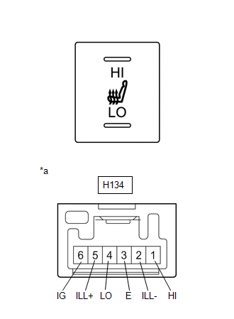
(b) Check the indicator illuminates.
(1) Apply battery voltage to the seat heater switch and check that the seat heater switch indicator illuminates.
OK:| Measurement Connection | Switch Condition | Specified Condition |
|---|---|---|
| If the result is not as specified, replace the seat heater switch. | ||
| Battery positive (+) → H134-6 (IG) Battery negative (-) → H134-3 (E) | "HI" switch on | illuminates |
| Battery positive (+) → H134-6 (IG) Battery negative (-) → H134-3 (E) | "LO" switch on | illuminates |
(c) Check the illuminates.
(1) Apply battery voltage to the seat heater switch and check that the seat heater switch illuminates.
OK:| Measurement Connection | Switch Condition | Specified Condition |
|---|---|---|
| If the result is not as specified, replace the seat heater switch. | ||
| Battery positive (+) → H134-5 (ILL+) Battery negative (-) → H134-2 (ILL-) | Always | illuminates |
 Removal
REMOVAL PROCEDURE 1. REMOVE SWITCH HOLE BASE SUB-ASSEMBLY Click here
2. REMOVE SEAT HEATER SWITCH (a) Disengage claws to remove the seat heater switch HINT: Use the same procedures for the opposite side...
 Installation
INSTALLATION PROCEDURE 1. INSTALL SEAT HEATER SWITCH (a) Engage the claws to install the seat heater switch. HINT: Use the same procedures for the opposite side...
Other information:
Toyota Yaris XP210 (2020-2026) Reapir and Service Manual: Throttle / Pedal Position Sensor / Switch "A" Circuit Short to Ground (P012011)
DESCRIPTION The throttle position sensor is built into the throttle body with motor assembly and detects the opening angle of the throttle valve. This sensor is a non-contact type sensor. It uses Hall-effect elements in order to yield accurate signals even in extreme driving conditions, such as at high speeds as well as very low speeds...
Toyota Yaris XP210 (2020-2026) Reapir and Service Manual: Check For Intermittent Problems
CHECK FOR INTERMITTENT PROBLEMS HINT: Inspect the vehicle ECM using check mode. Intermittent problems are easier to detect with the GTS when the ECM is in check mode. In check mode, the ECM uses 1 trip detection logic, which is more sensitive to malfunctions than normal mode (default), which uses 2 trip detection logic...
Categories
- Manuals Home
- Toyota Yaris Owners Manual
- Toyota Yaris Service Manual
- Headlights
- Auto Lock/Unlock Function
- Key Battery Replacement
- New on site
- Most important about car
Refueling
Before refueling, close all the doors, windows, and the liftgate/trunk lid, and switch the ignition OFF.
To open the fuel-filler lid, pull the remote fuel-filler lid release.
