Toyota Yaris: Front Door Lock / Inspection
INSPECTION
PROCEDURE
1. INSPECT FRONT DOOR WITH MOTOR LOCK ASSEMBLY RH
| (a) Check the resistance of the lock and unlock switch. (1) Measure the resistance according to the value(s) in the table below. Standard Resistance:
If the result is not as specified, replace the front door with motor lock assembly RH. |
|
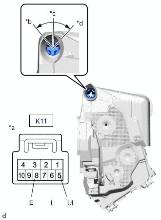
| (b) Check the door lock motor operation. (1) Apply auxiliary battery voltage to the motor connector and check the operation of the door lock motor. OK:
If the result is not as specified, replace the front door with motor lock assembly RH. |
|
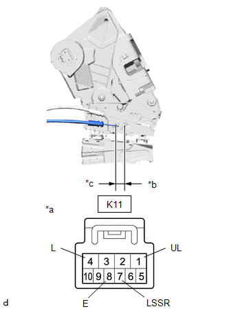
(c) Check the operation of the door unlock detection switch. (w/ Smart Entry and Start System)
(1) Measure the resistance according to the value(s) in the table below.
Standard Resistance:
| Tester Connection | Condition | Specified Condition |
|---|---|---|
| K11-7(LSSR) - K11-8(E) | Lock | 10 kΩ or higher |
| K11-7(LSSR) - K11-8(E) | Unlock | Below 1 Ω |
If the result is not as specified, replace the front door with motor lock assembly RH.
2. INSPECT FRONT DOOR WITH MOTOR LOCK ASSEMBLY LH
| (a) Check the resistance of the lock and unlock switch. (1) Measure the resistance according to the value(s) in the table below. Standard Resistance:
If the result is not as specified, replace the front door with motor lock assembly LH. |
|
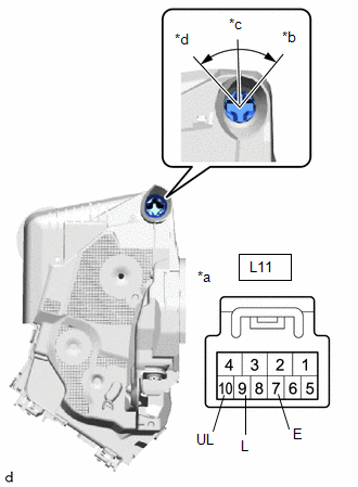
| (b) Check the door lock motor operation. (1) Apply auxiliary battery voltage to the motor connector and check the operation of the door lock motor. OK:
If the result is not as specified, replace the front door with motor lock assembly LH. |
|
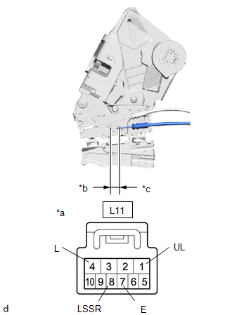
(c) Check the operation of the door unlock detection switch. (w/ Smart Entry and Start System)
(1) Measure the resistance according to the value(s) in the table below.
Standard Resistance:
| Tester Connection | Condition | Specified Condition |
|---|---|---|
| L11-7(E) - L11-8(LSSR) | Lock | 10 kΩ or higher |
| L11-7(E) - L11-8(LSSR) | Unlock | Below 1 Ω |
If the result is not as specified, replace the front door with motor lock assembly LH.
 Removal
REMOVAL CAUTION / NOTICE / HINT The necessary procedures (adjustment, calibration, initialization, or registration) that must be performed after parts are removed and installed, or replaced during the front door with motor lock assembly removal/installation are shown below...
 Installation
INSTALLATION CAUTION / NOTICE / HINT HINT:
Use the same procedure for the LH side and RH side.
The following procedure is for the LH side.
PROCEDURE 1...
Other information:
Toyota Yaris XP210 (2020-2026) Reapir and Service Manual: Ea67f Manual Transaxle Oil
ComponentsCOMPONENTS ILLUSTRATION *1 NO. 1 ENGINE UNDER COVER ASSEMBLY *2 ENGINE UNDER COVER LH *3 MANUAL TRANSMISSION FILLER PLUG *4 MANUAL TRANSMISSION DRAIN PLUG *5 GASKET - - N*m (kgf*cm, ft.*lbf): Specified torque ● Non-reusable part ReplacementREPLACEMENT PROCEDURE 1...
Toyota Yaris XP210 (2020-2026) Reapir and Service Manual: Engine Coolant Temperature Receiver Gauge Malfunction
DESCRIPTION In this circuit, the combination meter assembly receives engine coolant temperature signals from the ECM via CAN communication. The combination meter assembly displays an engine coolant temperature warning based on the data received from the ECM...
Categories
- Manuals Home
- Toyota Yaris Owners Manual
- Toyota Yaris Service Manual
- Power Integration No.1 System Missing Message (B235287,B235587,B235787-B235987)
- Key Battery Replacement
- Headlights
- New on site
- Most important about car
Keys

To use the auxiliary key, press the knob and pull out the auxiliary key from the smart key.
