Toyota Yaris: Brake Pedal / Installation
INSTALLATION
PROCEDURE
1. INSTALL BRAKE PEDAL PAD
(a) Install the brake pedal pad to the brake pedal support assembly.
2. INSTALL BRAKE PEDAL SUPPORT ASSEMBLY
(a) Engage the 2 clamps to install the wire harness to the brake pedal support assembly.
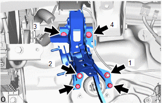
(b) Temporarily install the brake pedal support assembly with the 2 bolts and 2 nuts.
| (c) Tighten the 2 nuts and 2 bolts in the order shown in the illustration. Torque: 12.7 N·m {130 kgf·cm, 9 ft·lbf} |
|
(d) Install 2 new clips.
(e) Engage the clamp to install the wire harness to the brake pedal support assembly.
3. INSTALL PUSH ROD PIN
(a) Apply lithium soap base glycol grease to the push rod pin and installation hole of the brake pedal support assembly.
 | Lithium soap base glycol grease |
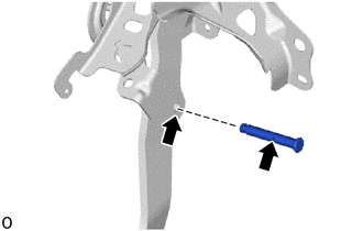
(b) Connect the brake master cylinder push rod clevis to the brake pedal support assembly with the push rod pin, and install a new clip.
NOTICE:
Be sure to install the push rod pin in the correct direction.
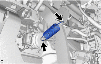
4. INSTALL BRAKE PEDAL RETURN SPRING
| (a) Install the brake pedal return spring to the brake pedal support assembly as shown in the illustration. |
|
5. INSTALL STOP LIGHT SWITCH MOUNTING ADJUSTER
Click here

6. INSTALL STOP LIGHT SWITCH ASSEMBLY
Click here

7. INSTALL STEERING COLUMN ASSEMBLY
Click here

8. INSPECT AND ADJUST BRAKE PEDAL
Click here

 Adjustment
ADJUSTMENT PROCEDURE 1. INSPECT AND ADJUST BRAKE PEDAL HEIGHT (a) Remove front door scuff plate LH. Click here
(b) Remove cowl side trim board LH. Click here
(c) Turn back floor carpet...
 Brake System
PrecautionPRECAUTION NOTICE:
This vehicle is equipped with an SRS (Supplemental Restraint System). Failure to carry out service operations in the correct sequence could cause the SRS to unexpectedly deploy during servicing...
Other information:
Toyota Yaris XP210 (2020-2026) Owner's Manual: Liftgate/Trunk Lid
WARNING Never allow a person to ride in the luggage compartment/trunk Allowing a person to ride in the luggage compartment/trunk is dangerous. The person in the luggage compartment/trunk could be seriously injured or killed during sudden braking or a collision...
Toyota Yaris XP210 (2020-2026) Reapir and Service Manual: Installation
INSTALLATION PROCEDURE 1. INSTALL CHARCOAL CANISTER OUTLET HOSE (a) Engage the clamp to install the charcoal canister outlet hose to the fuel tank assembly. 2. INSTALL FUEL TANK ASSEMBLY CAUTION: The fuel tank assembly is very heavy. Be sure to follow the procedure described in the repair manual, or the fuel tank assembly may fall off the engine lifter...
Categories
- Manuals Home
- Toyota Yaris Owners Manual
- Toyota Yaris Service Manual
- Brake System Control Module "A" System Voltage System Voltage Low (C137BA2)
- Key Battery Replacement
- To Set Speed
- New on site
- Most important about car
Fuel-Filler Lid and Cap
WARNING
When removing the fuel-filler cap, loosen the cap slightly and wait for any hissing to stop, then remove it
Fuel spray is dangerous. Fuel can burn skin and eyes and cause illness if ingested. Fuel spray is released when there is pressure in the fuel tank and the fuel-filler cap is removed too quickly.