Toyota Yaris: Outer Rear View Mirror / Inspection
INSPECTION
PROCEDURE
1. INSPECT OUTER REAR VIEW MIRROR ASSEMBLY LH
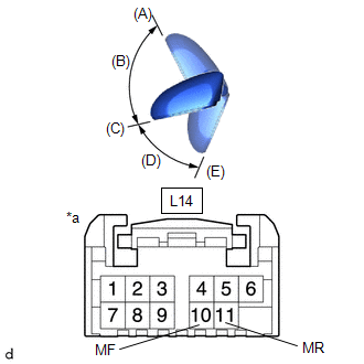
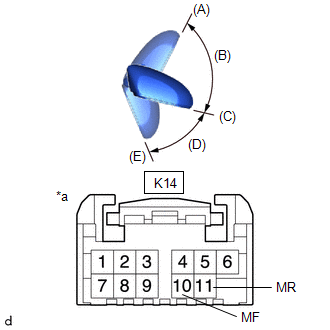
(a) Check the operation of the retractable mirror.
NOTICE:
- Disconnect and reconnect the auxiliary battery between each mirror position check.
- The mirror position cannot be changed manually when the Auxiliary battery is connected. To change the mirror position manually, the Auxiliary battery must be disconnected first.
- If the motor is kept energized, even after each mirror position check, it may lead to a motor malfunction. Make sure to disconnect the auxiliary battery immediately after performing each mirror position check.
| (1) For each position: Disconnect the auxiliary battery, set the mirror position by hand, connect the auxiliary battery, and check the retractable mirror movement. OK:
If the result is not as specified, replace the outer mirror retractor assembly LH. |
|
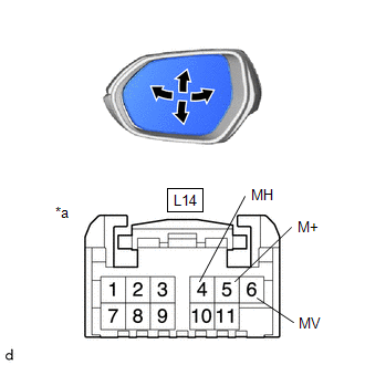
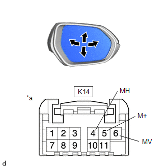
(b) Check the operation of the mirror surface.
| (1) Apply voltage and check the operation of the outer rear view mirror assembly LH. OK:
If the result is not as specified, replace the outer rear view mirror assembly LH. |
|
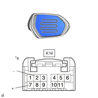
(c) Check the operation of the mirror heater.
| (1) Measure the resistance according to the value(s) in the table below. Standard Resistance:
If the result is not as specified, inspect the outer mirror LH or replace the outer rear view mirror assembly LH. |
|
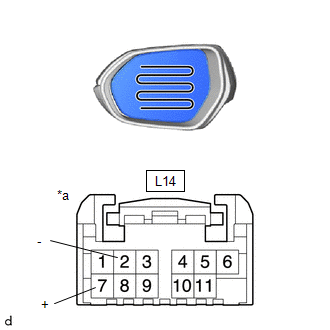
(2) Connect a cable from the positive (+) auxiliary battery terminal to L14-7 (+) and the negative (-) auxiliary battery terminal to L14-2 (2), then check that the mirror becomes warm.
HINT:
It takes a short time for the mirror to become warm.
OK:
Mirror becomes warm.
If the result is not as specified, inspect the outer mirror LH or replace the outer rear view mirror assembly LH.
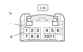
(d) Check the side turn signal light assembly LH.
| (1) Apply auxiliary battery voltage to the terminals of the connector, and check the illumination condition. OK:
If the result is not as specified, inspect the side turn signal light assembly LH or replace the outer rear view mirror assembly LH. |
|
2. INSPECT OUTER REAR VIEW MIRROR ASSEMBLY RH
(a) Check the operation of the retractable mirror.
NOTICE:
- Disconnect and reconnect the auxiliary battery between each mirror position check.
- The mirror position cannot be changed manually when the auxiliary battery is connected. To change the mirror position manually, the auxiliary battery must be disconnected first.
- If the motor is kept energized, even after each mirror position check, it may lead to a motor malfunction. Make sure to disconnect the auxiliary battery immediately after performing each mirror position check.
| (1) For each position: Disconnect the auxiliary battery, set the mirror position by hand, connect the auxiliary battery, and check the retractable mirror movement. OK:
If the result is not as specified, replace the outer mirror retractor assembly RH. |
|
(b) Check the operation of the mirror surface.
| (1) Apply voltage and check the operation of the outer rear view mirror assembly RH. OK:
If the result is not as specified, replace the outer rear view mirror assembly RH. |
|
(c) Check the operation of the mirror heater.
| (1) Measure the resistance according to the value(s) in the table below. Standard Resistance:
If the result is not as specified, inspect the outer mirror RH or replace the outer rear view mirror assembly RH. |
|
(2) Connect a cable from the positive (+) auxiliary battery terminal to K14-7 (+) and negative (-) auxiliary battery terminal to K14-2 (-), then check that the mirror becomes warm.
HINT:
It takes a short time for the mirror to become warm.
OK:
Mirror becomes warm.
If the result is not as specified, inspect the outer mirror RH or replace the outer rear view mirror assembly RH.
(d) Check the side turn signal light assembly RH.
| (1) Apply auxiliary battery voltage to the terminals of the connector, and check the illumination condition. OK:
If the result is not as specified, inspect the side turn signal light assembly RH or replace the outer rear view mirror assembly RH. |
|

 Disassembly
DISASSEMBLY CAUTION / NOTICE / HINT HINT:
Use the same procedure for the RH side and LH side.
The following procedure is for the LH side.
PROCEDURE 1...
 Reassembly
REASSEMBLY CAUTION / NOTICE / HINT HINT:
Use the same procedure for the RH side and LH side.
The following procedure is for the LH side.
PROCEDURE 1...
Other information:
Toyota Yaris XP210 (2020-2026) Reapir and Service Manual: Lost Communication with ECM/PCM "A" Missing Message (U010087,U010187,U012687,U012987,U013187,U015587)
DESCRIPTION When a communication malfunction is detected between the forward recognition camera and an ECU or sensor, a DTC is stored. DTC No. Detection Item DTC Detection Condition Trouble Area U010087 Lost Communication with ECM/PCM "A" Missing Message When the ignition switch is ON for 3 seconds or more, a communication malfunction between the forward recognition camera and the ECM continues for approximately 2 seconds or more...
Toyota Yaris XP210 (2020-2026) Reapir and Service Manual: Installation
INSTALLATION CAUTION / NOTICE / HINT NOTICE: After performing the update ECU security key procedure, make sure to perform the initialization procedure for when the cable has been disconnected and reconnected to the negative (-) auxiliary battery terminal...
Categories
- Manuals Home
- Toyota Yaris Owners Manual
- Toyota Yaris Service Manual
- Opening and Closing the Liftgate/Trunk Lid
- Power Integration No.1 System Missing Message (B235287,B235587,B235787-B235987)
- How to use USB mode
- New on site
- Most important about car
Front Seat Belt Pretensioners
The front seat belt pretensioners are designed to deploy in moderate or severe frontal, near frontal collisions.
In addition, the pretensioners operate when a side collision or a rollover accident is detected. The pretensioners operate differently depending on what types of air bags are equipped. For more details about the seat belt pretensioner operation, refer to the SRS Air Bag Deployment Criteria.