Toyota Yaris: Outer Rear View Mirror / Reassembly
REASSEMBLY
CAUTION / NOTICE / HINT
HINT:
- Use the same procedure for the RH side and LH side.
- The following procedure is for the LH side.
PROCEDURE
1. INSTALL OUTER MIRROR RETRACTOR
| (a) Install a new wire harness to a new outer mirror retractor. |
|
.png)
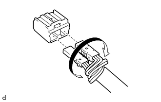
(b) Connect the connector.
| (c) Install the outer mirror retractor with the 3 screws. |
|
.png)
| (d) Connect the connector. |
|
.png)
| (e) Engage the guide to install the power unit assembly. |
|
.png)
(f) Install the 3 new screws.
| (g) Install the base with the 3 new screws. NOTICE:
|
|
.png)
| (h) Engage the guides to install a new gasket. NOTICE: Do not make gaps between the base and gasket. |
|
.png)
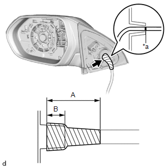
| (i) Rotate the connector and twist the longer wire harness as shown in the illustration. |
|
(j) Connect each connector to a new adapter.
| (k) Install a new vinyl tape as shown in the illustration. Reference Measurement:
|
|
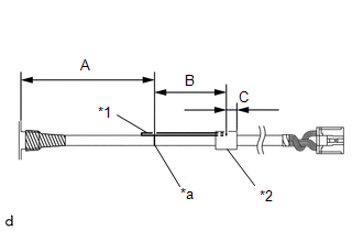
| (l) Install a new bar with a new tape to the wire harness as shown in the illustration. Reference Measurement
|
|
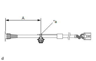
| (m) Install a new clip to the wire harness as shown in the illustration. Reference Measurement
|
|
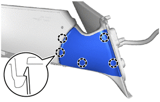
2. INSTALL OUTER MIRROR HOLE COVER
| (a) Engage the claws to install a new outer mirror hole cover. |
|
3. INSTALL SIDE TURN SIGNAL LIGHT ASSEMBLY
Click here
.gif)
4. INSTALL OUTER MIRROR LOWER COVER
| (a) Engage the claws to install the outer mirror lower cover. |
|
.png)
(b) Install the screw.
5. INSTALL OUTER MIRROR COVER
Click here
6. INSTALL OUTER MIRROR
Click here
 Inspection
INSPECTION PROCEDURE 1. INSPECT OUTER REAR VIEW MIRROR ASSEMBLY LH (a) Check the operation of the retractable mirror. NOTICE:
Disconnect and reconnect the auxiliary battery between each mirror position check...
 Installation
INSTALLATION CAUTION / NOTICE / HINT HINT:
Use the same procedure for the RH side and LH side.
The following procedure is for the LH side.
PROCEDURE 1...
Other information:
Toyota Yaris XP210 (2020-2026) Reapir and Service Manual: Manifold Absolute Pressure / Barometric Pressure Sensor Circuit Short to Battery or Open (P010515)
DESCRIPTION Refer to DTC P010511. Click here DTC No. Detection Item DTC Detection Condition Trouble Area MIL Note P010515 Manifold Absolute Pressure / Barometric Pressure Sensor Circuit Short to Battery or Open The No. 1 turbo pressure sensor output voltage is higher than 4...
Toyota Yaris XP210 (2020-2026) Reapir and Service Manual: Problem Symptoms Table
PROBLEM SYMPTOMS TABLE If there are no DTCs output and the problem still occurs, check the suspected areas for each problem symptom in the order given in the following table and proceed to the relevant troubleshooting page. NOTICE: When replacing the skid control ECU (brake actuator assembly), sensors, etc...
Categories
- Manuals Home
- Toyota Yaris Owners Manual
- Toyota Yaris Service Manual
- Headlights
- Opening and Closing the Liftgate/Trunk Lid
- Brake System Control Module "A" System Voltage System Voltage Low (C137BA2)
- New on site
- Most important about car
Keys

To use the auxiliary key, press the knob and pull out the auxiliary key from the smart key.
