Toyota Yaris: Smart Key System (for Start Function) / Vehicle Speed Signal Circuit Open (B228231,B228262)
DESCRIPTION
DTC B228231 is stored when the vehicle speed signal sent by the combination meter assembly via direct line and the vehicle speed signal sent via CAN communication do not match.
DTC B228262 is stored when a malfunction in the vehicle speed sensor is detected.
| DTC No. | Detection Item | DTC Detection Condition | Trouble Area | Note |
|---|---|---|---|---|
| B228231 | Vehicle Speed Signal Circuit Open | The vehicle speed signal sent by the combination meter assembly via direct line and the vehicle speed signal sent via CAN communication do not match. (1-trip detection logic*) |
|
|
| B228262 | Vehicle Speed Signal Compare Failure | Vehicle speed signal malfunction is detected (excessive deceleration is detected). (1-trip detection logic*) |
|
|
- *: Only detected while a malfunction is present and the ignition switch is ON.
| DTC Code | Vehicle Condition when Malfunction Detected | Fail-safe Function when Malfunction Detected |
|---|---|---|
| B228231 |
| - |
| B228262 |
| Steering lock motor operation is prohibited. |
| DTC No. | Data List and Active Test |
|---|---|
| B228231 B228262 | Power Source Control
Combination Meter
|
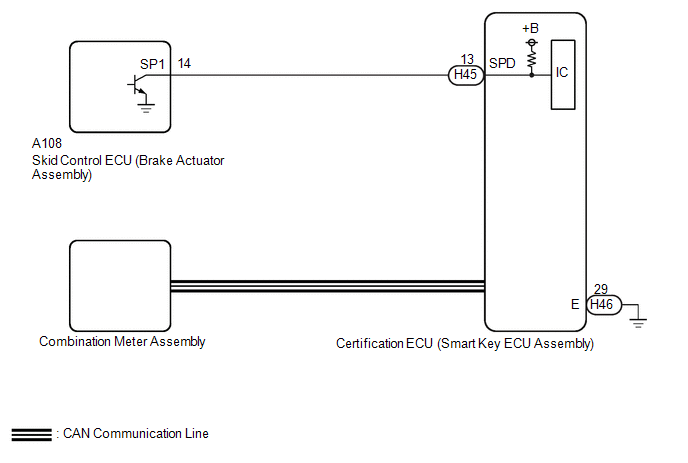
WIRING DIAGRAM
CAUTION / NOTICE / HINT
NOTICE:
- When using the GTS with the ignition switch off, connect the GTS to the DLC3 and turn a courtesy light switch on and off at intervals of 1.5 seconds or less until communication between the GTS and the vehicle begins. Then select the vehicle type under manual mode and enter the following menus: Body Electrical / Smart Key. While using the GTS, periodically turn a courtesy light switch on and off at intervals of 1.5 seconds or less to maintain communication between the GTS and the vehicle.
-
The smart key system (for Start Function) uses the LIN communication system and CAN communication system. Inspect the communication function by following How to Proceed with Troubleshooting. Troubleshoot the smart key system (for Start Function) after confirming that the communication systems are functioning properly.
Click here

-
Before replacing the certification ECU (smart key ECU assembly), refer to Registration.
Click here

- After repair, confirm that no DTCs are output by performing "DTC Output Confirmation Operation".
PROCEDURE
| 1. | READ VALUE USING GTS (VEHICLE SPEED METER) |
(a) Read the Data List according to the display on the GTS.
Body Electrical > Combination Meter > Data List| Tester Display | Measurement Item | Range | Normal Condition | Diagnostic Note |
|---|---|---|---|---|
| Vehicle Speed Meter | Vehicle speed | Min.: 0, Max.: 255 | Almost same as actual vehicle speed (Speedometer tester) | - |
| Tester Display |
|---|
| Vehicle Speed Meter |
HINT:
Using a speedometer tester, check the actual vehicle speed and the vehicle speed displayed on the GTS.
OK:
Vehicle speed displayed on the GTS is almost the same as the actual vehicle speed measured using a speedometer tester.
| NG |
 | GO TO METER / GAUGE SYSTEM (Speedometer Malfunction) |
|

| 2. | READ VALUE USING GTS (VEHICLE RUNNING CONDITION (LINE)) |
(a) Read the Data List according to the display on the GTS.
Body Electrical > Power Source Control > Data List| Tester Display | Measurement Item | Range | Normal Condition | Diagnostic Note |
|---|---|---|---|---|
| Vehicle Running Condition (Line) | Vehicle being driven or stopped | Stop or Driving | Stop: Vehicle stopped | - |
| Tester Display |
|---|
| Vehicle Running Condition (Line) |
OK:
The GTS display changes correctly in response to the vehicle condition.
| Result | Proceed to |
|---|---|
| The value of Vehicle Running Condition (Line) is Stop | A |
| The value of Vehicle Running Condition (Line) is not Stop | B |
| B |
 | GO TO STEP 4 |
|

| 3. | READ VALUE USING GTS (VEHICLE RUNNING CONDITION (LINE)) |
(a) Read the Data List according to the display on the GTS.
Body Electrical > Power Source Control > Data List| Tester Display | Measurement Item | Range | Normal Condition | Diagnostic Note |
|---|---|---|---|---|
| Vehicle Running Condition (Line) | Vehicle being driven or stopped | Stop or Driving | Driving: Vehicle being driven at 5 km/h (3 mph) or more | - |
| Tester Display |
|---|
| Vehicle Running Condition (Line) |
OK:
The GTS display changes correctly in response to the vehicle condition.
| Result | Proceed to |
|---|---|
| The value of Vehicle Running Condition (Line) is Driving | A |
| The value of Vehicle Running Condition (Line) is not Driving | B |
| A |
 | GO TO METER / GAUGE SYSTEM (HOW TO PROCEED WITH TROUBLESHOOTING) |
|

| 4. | CHECK HARNESS AND CONNECTOR (CERTIFICATION ECU (SMART KEY ECU ASSEMBLY) - SKID CONTROL ECU (BRAKE ACTUATOR ASSEMBLY)) |
(a) Disconnect the A108 skid control ECU (brake actuator assembly) connector.
(b) Disconnect the H45 certification ECU (smart key ECU assembly) connector.
(c) Measure the resistance according to the value(s) in the table below.
Standard Resistance:
| Tester Connection | Condition | Specified Condition |
|---|---|---|
| H45-13 (SPD) - A108-14 (SP1) | Always | Below 1 Ω |
| H45-13 (SPD) or A108-14 (SP1) - Other terminals and body ground | Always | 10 kΩ or higher |
| NG |
 | REPAIR OR REPLACE HARNESS OR CONNECTOR |
|

| 5. | CHECK CERTIFICATION ECU (SMART KEY ECU ASSEMBLY) |
(a) Connect the H45 certification ECU (smart key ECU assembly) connector.
(b) Connect the A108 skid control ECU (brake actuator assembly) connector.
(c) Using an oscilloscope, check the waveform.
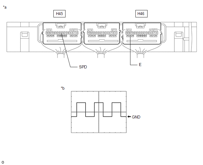
| *a | Component with harness connected (Certification ECU (Smart Key ECU Assembly)) | *b | Waveform |
OK:
| Tester Connection | Condition | Tool Setting | Specified Condition |
|---|---|---|---|
| H45-13 (SPD) - H46-29 (E) | Ignition switch ON, vehicle being driven at approx. 5 km/h (3 mph) | 5 V/DIV., 20 ms./DIV. | Pulse generation (See waveform) |
HINT:
The wavelength becomes shorter as the vehicle speed increases.
| OK |
 | REPLACE CERTIFICATION ECU (SMART KEY ECU ASSEMBLY) |
| NG |
 | GO TO VEHICLE STABILITY CONTROL SYSTEM (HOW TO PROCEED WITH TROUBLESHOOTING) |
 Engine/Power Switch Signal Compare Failure (B227862)
DESCRIPTION This DTC is stored when the SSW1 contact signal, SSW2 contact signal and SSW3 contact signal, which are detected when the engine switch is operated, do not match...
 Steering Lock Position Signal Compare Failure (B228562)
DESCRIPTION This DTC is stored when the steering lock position signal sent by the steering lock ECU (steering lock actuator or upper bracket assembly) via direct line and the steering lock position signal sent via LIN communication do not match...
Other information:
Toyota Yaris XP210 (2020-2026) Reapir and Service Manual: Removal
REMOVAL PROCEDURE 1. REMOVE CENTER LOWER INSTRUMENT COVER Click here 2. REMOVE LOWER INSTRUMENT PANEL FINISH PANEL Click here 3. REMOVE SWITCH HOLE BASE SUB-ASSEMBLY Click here 4. REMOVE SHIFT LEVER KNOB SUB-ASSEMBLY Click here 5. REMOVE CONSOLE BOX ASSEMBLY Click here 6...
Toyota Yaris XP210 (2020-2026) Reapir and Service Manual: Starter Relay Signal Compare Failure (P061562)
DESCRIPTION When the STA signal detected by the ECM and by the engine stop and start ECU do not match, the engine stop and start ECU stores DTC P061562 and blinks the stop and start cancel indicator. DTC No. Detection Item DTC Detection Condition Trouble Area Warning Indicate Memory Note P061562 Starter Relay Signal Compare Failure Both of the following conditions are met for 2 seconds or more (1 trip detection logic): Normal communication with the ECM...
Categories
- Manuals Home
- Toyota Yaris Owners Manual
- Toyota Yaris Service Manual
- Key Battery Replacement
- Diagnostic Trouble Code Chart
- Battery Monitor Module General Electrical Failure (P058A01)
- New on site
- Most important about car
Break-In Period
No special break-in is necessary, but a few precautions in the first 600 miles (1,000 km) may add to the performance, economy, and life of the vehicle.
Do not race the engine. Do not maintain one constant speed, either slow or fast, for a long period of time. Do not drive constantly at full-throttle or high engine rpm for extended periods of time. Avoid unnecessary hard stops. Avoid full-throttle starts.