Toyota Yaris: Smart Key System (for Start Function) / Engine/Power Switch Signal Compare Failure (B227862)
DESCRIPTION
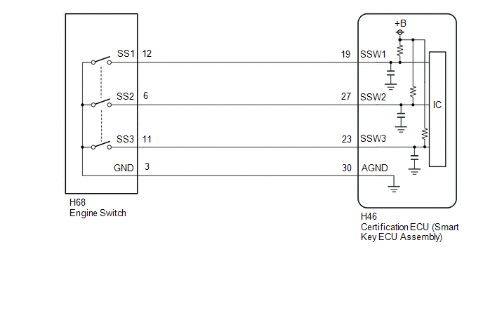
This DTC is stored when the SSW1 contact signal, SSW2 contact signal and SSW3 contact signal, which are detected when the engine switch is operated, do not match.
| DTC No. | Detection Item | DTC Detection Condition | Trouble Area | Note |
|---|---|---|---|---|
| B227862 | Engine/Power Switch Signal Compare Failure | When the engine switch is operated, the SSW1 contact signal, SSW2 contact signal and SSW3 contact signal do not match. |
|
|
| Vehicle Condition when Malfunction Detected | Fail-safe Function when Malfunction Detected |
|---|---|
| If there is a malfunction in only one of the terminals SS1, SS2 or SS3, the system can still operate normally. | When only one terminal malfunctions, that terminal is disabled and the system operates normally. |
| DTC No. | Data List and Active Test |
|---|---|
| B227862 | Power Source Control
|
WIRING DIAGRAM
CAUTION / NOTICE / HINT
NOTICE:
- When using the GTS with the ignition switch off, connect the GTS to the DLC3 and turn a courtesy light switch on and off at intervals of 1.5 seconds or less until communication between the GTS and the vehicle begins. Then select the vehicle type under manual mode and enter the following menus: Body Electrical / Smart Key. While using the GTS, periodically turn a courtesy light switch on and off at intervals of 1.5 seconds or less to maintain communication between the GTS and the vehicle.
-
The smart key system (for Start Function) uses the LIN communication system and CAN communication system. Inspect the communication function by following How to Proceed with Troubleshooting. Troubleshoot the smart key system (for Start Function) after confirming that the communication systems are functioning properly.
Click here

-
Before replacing the certification ECU (smart key ECU assembly), refer to Registration.
Click here

- After repair, confirm that no DTCs are output by performing "DTC Output Confirmation Operation".
PROCEDURE
| 1. | READ VALUE USING GTS (PUSH START SWITCH 1, PUSH START SWITCH 2, PUSH START SWITCH 3) |
(a) Read the Data List according to the display on the GTS.
Body Electrical > Power Source Control > Data List| Tester Display | Measurement Item | Range | Normal Condition | Diagnostic Note |
|---|---|---|---|---|
| Push Start Switch 1 | Engine switch 1 status | OFF or ON | OFF: Engine switch not pressed ON: Engine switch pressed |
|
| Push Start Switch 2 | Engine switch 2 status | OFF or ON | OFF: Engine switch not pressed ON: Engine switch pressed |
|
| Push Start Switch 3 | Engine switch 3 status | OFF or ON | OFF: Engine switch not pressed ON: Engine switch pressed |
|
| Tester Display |
|---|
| Push Start Switch 1 |
| Push Start Switch 2 |
| Push Start Switch 3 |
OK:
The GTS display changes correctly in response to the engine switch operation.
| NG |
 | GO TO STEP 3 |
|

| 2. | READ VALUE USING GTS (PUSH START SWITCH 1, PUSH START SWITCH 2, PUSH START SWITCH 3) |
(a) According to the display on the GTS, read the Data List while wiggling the wire harness.
Body Electrical > Power Source Control > Data List| Tester Display | Measurement Item | Range | Normal Condition | Diagnostic Note |
|---|---|---|---|---|
| Push Start Switch 1 | Engine switch 1 status | OFF or ON | OFF: Engine switch not pressed ON: Engine switch pressed |
|
| Push Start Switch 2 | Engine switch 2 status | OFF or ON | OFF: Engine switch not pressed ON: Engine switch pressed |
|
| Push Start Switch 3 | Engine switch 3 status | OFF or ON | OFF: Engine switch not pressed ON: Engine switch pressed |
|
| Tester Display |
|---|
| Push Start Switch 1 |
| Push Start Switch 2 |
| Push Start Switch 3 |
OK:
The GTS display changes correctly in response to the engine switch operation.
| OK |
 | USE SIMULATION METHOD TO CHECK |
| NG |
 | REPAIR OR REPLACE HARNESS OR CONNECTOR |
| 3. | CHECK HARNESS AND CONNECTOR (CERTIFICATION ECU (SMART KEY ECU ASSEMBLY) - ENGINE SWITCH) |
(a) Disconnect the H46 certification ECU (smart key ECU assembly) connector.
(b) Disconnect the H68 engine switch connector.
(c) Measure the resistance according to the value(s) in the table below.
Standard Resistance:
| Tester Connection | Condition | Specified Condition |
|---|---|---|
| H46-19 (SSW1) - H68-12 (SS1) | Always | Below 1 Ω |
| H46-27 (SSW2) - H68-6 (SS2) | Always | Below 1 Ω |
| H46-23 (SSW3) - H68-11 (SS3) | Always | Below 1 Ω |
| H46-30 (AGND) - H68-3 (GND) | Always | Below 1 Ω |
| H46-19 (SSW1) or H68-12 (SS1) - Other terminals and body ground | Always | 10 kΩ or higher |
| H46-27 (SSW2) or H68-6 (SS2) - Other terminals and body ground | Always | 10 kΩ or higher |
| H46-23 (SSW3) or H68-11 (SS3) - Other terminals and body ground | Always | 10 kΩ or higher |
| H46-30 (AGND) or H68-3 (GND) - Other terminals and body ground | Always | 10 kΩ or higher |
| NG |
 | REPAIR OR REPLACE HARNESS OR CONNECTOR |
|

| 4. | INSPECT ENGINE SWITCH |
Click here

| OK |
 | REPLACE CERTIFICATION ECU (SMART KEY ECU ASSEMBLY) |
| NG |
 | REPLACE ENGINE SWITCH |
 ACC Circuit Short to Ground (B227411)
DESCRIPTION This DTC is stored when a malfunction in the ACC output circuit is detected. The ACC output circuit is the circuit between terminal ACCD of the certification ECU (smart key ECU assembly) and the ACC relay...
 Vehicle Speed Signal Circuit Open (B228231,B228262)
DESCRIPTION DTC B228231 is stored when the vehicle speed signal sent by the combination meter assembly via direct line and the vehicle speed signal sent via CAN communication do not match...
Other information:
Toyota Yaris XP210 (2020-2026) Owner's Manual: Specifications
Engine Electrical System *: The spark plugs provide the engine its optimum performance. Consult your Toyota dealer for details. NOTICE When cleaning the iridium plugs, do not use a wire brush. The fine particulate coating on the iridium alloy and platinum tips could be damaged...
Toyota Yaris XP210 (2020-2026) Reapir and Service Manual: Components
C..
Categories
- Manuals Home
- Toyota Yaris Owners Manual
- Toyota Yaris Service Manual
- How to use USB mode
- Power Integration No.1 System Missing Message (B235287,B235587,B235787-B235987)
- Headlights
- New on site
- Most important about car
Fuel Gauge
The fuel gauge shows approximately how much fuel is remaining in the tank when the ignition is switched ON. We recommend keeping the tank over 1/4 full.
