Toyota Yaris: Smart Key System (for Start Function) / Steering Lock Position Signal Compare Failure (B228562)
DESCRIPTION
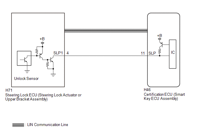
This DTC is stored when the steering lock position signal sent by the steering lock ECU (steering lock actuator or upper bracket assembly) via direct line and the steering lock position signal sent via LIN communication do not match.
| DTC No. | Detection Item | DTC Detection Condition | Trouble Area | Note |
|---|---|---|---|---|
| B228562 | Steering Lock Position Signal Compare Failure | The steering lock position signal sent by the steering lock ECU (steering lock actuator or upper bracket assembly) via direct line and the steering lock position signal sent via LIN communication do not match. (1-trip detection logic*) |
|
|
- *: Only detected while a malfunction is present and the ignition switch is ON.
| Vehicle Condition when Malfunction Detected | Fail-safe Function when Malfunction Detected |
|---|---|
| The engine cannot be started. | The ECU does not send an engine start request. |
| DTC No. | Data List and Active Test |
|---|---|
| B228562 | Power Source Control
Smart Key
|
WIRING DIAGRAM
CAUTION / NOTICE / HINT
NOTICE:
- When using the GTS with the ignition switch off, connect the GTS to the DLC3 and turn a courtesy light switch on and off at intervals of 1.5 seconds or less until communication between the GTS and the vehicle begins. Then select the vehicle type under manual mode and enter the following menus: Body Electrical / Smart Key. While using the GTS, periodically turn a courtesy light switch on and off at intervals of 1.5 seconds or less to maintain communication between the GTS and the vehicle.
-
The smart key system (for Start Function) uses the LIN communication system and CAN communication system. Inspect the communication function by following How to Proceed with Troubleshooting. Troubleshoot the smart key system (for Start Function) after confirming that the communication systems are functioning properly.
Click here

- Inspect the fuses for circuits related to this system before performing the following procedure.
-
Before replacing the certification ECU (smart key ECU assembly) or steering lock ECU (steering lock actuator or upper bracket assembly), refer to Registration.
Click here

- After repair, confirm that no DTCs are output by performing "DTC Output Confirmation Operation".
PROCEDURE
| 1. | CHECK FOR DTC |
(a) Check for DTCs.
Body Electrical > Smart Key > Trouble CodesHINT:
- If the steering cannot be unlocked, the ignition switch cannot be turned to ON and the engine cannot be started.
- If LIN communication is not available, the steering cannot be locked or unlocked.
OK:
LIN communication system DTC B278588 is not output simultaneously.
| NG |
 | GO TO DTC B278588 |
|

| 2. | INSPECT CERTIFICATION ECU (SMART KEY ECU ASSEMBLY) |
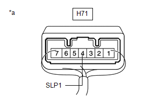
(a) Disconnect the H71 steering lock ECU (steering lock actuator or upper bracket assembly) connector.
(b) Measure the voltage according to the value(s) in the table below.
Standard Voltage:
| Tester Connection | Condition | Specified Condition |
|---|---|---|
| H71-4 (SLP1) - Body ground | Steering locked | 11 to 14 V |
| H71-4 (SLP1) - Body ground | Steering unlocked | Below 1.5 V |
(c) Reconnect the H71 steering lock ECU (steering lock actuator or upper bracket assembly) connector.
| NG |
 | GO TO STEP 6 |
|

| 3. | READ VALUE USING GTS (STEERING UNLOCK SWITCH) |
(a) Read the Data List according to the display on the GTS.
Body Electrical > Power Source Control > Data List| Tester Display | Measurement Item | Range | Normal Condition | Diagnostic Note |
|---|---|---|---|---|
| Steering Unlock Switch | State of steering unlock sensor signal output from steering lock ECU (steering lock actuator or upper bracket assembly) | OFF or ON | OFF: Steering locked |
|
| Tester Display |
|---|
| Steering Unlock Switch |
OK:
The GTS display changes.
| Result | Proceed to |
|---|---|
| The value of Steering Unlock Switch is OFF | A |
| The value of Steering Unlock Switch is not OFF | B |
| B |
 | REPLACE STEERING LOCK ECU (STEERING LOCK ACTUATOR OR UPPER BRACKET ASSEMBLY) |
|

| 4. | READ VALUE USING GTS (STEERING UNLOCK SWITCH) |
(a) Read the Data List according to the display on the GTS.
Body Electrical > Power Source Control > Data List| Tester Display | Measurement Item | Range | Normal Condition | Diagnostic Note |
|---|---|---|---|---|
| Steering Unlock Switch | State of steering unlock sensor signal output from steering lock ECU (steering lock actuator or upper bracket assembly) | OFF or ON | ON: Steering unlocked |
|
| Tester Display |
|---|
| Steering Unlock Switch |
OK:
The GTS display changes.
| Result | Proceed to |
|---|---|
| The value of Steering Unlock Switch is ON | A |
| The value of Steering Unlock Switch is not ON | B |
| B |
 | REPLACE STEERING LOCK ECU (STEERING LOCK ACTUATOR OR UPPER BRACKET ASSEMBLY) |
|

| 5. | CHECK STEERING LOCK ECU (STEERING LOCK ACTUATOR OR UPPER BRACKET ASSEMBLY) |
| (a) Measure the resistance according to the value(s) in the table below. Standard Resistance:
HINT:
|
|
| NG |
 | REPLACE STEERING LOCK ECU (STEERING LOCK ACTUATOR OR UPPER BRACKET ASSEMBLY) |
|

| 6. | CHECK HARNESS AND CONNECTOR (CERTIFICATION ECU (SMART KEY ECU ASSEMBLY) - STEERING LOCK ECU (STEERING LOCK ACTUATOR OR UPPER BRACKET ASSEMBLY)) |
(a) Disconnect the H46 certification ECU (smart key ECU assembly) connector.
(b) Disconnect the H71 steering lock ECU (steering lock actuator or upper bracket assembly) connector.
(c) Measure the resistance according to the value(s) in the table below.
Standard Resistance:
| Tester Connection | Condition | Specified Condition |
|---|---|---|
| H46-11 (SLP) - H71-4 (SLP1) | Always | Below 1 Ω |
| H46-11 (SLP) or H71-4 (SLP1) - Other terminals and body ground | Always | 10 kΩ or higher |
| OK |
 | REPLACE CERTIFICATION ECU (SMART KEY ECU ASSEMBLY) |
| NG |
 | REPAIR OR REPLACE HARNESS OR CONNECTOR |
 Vehicle Speed Signal Circuit Open (B228231,B228262)
DESCRIPTION DTC B228231 is stored when the vehicle speed signal sent by the combination meter assembly via direct line and the vehicle speed signal sent via CAN communication do not match...
 Battery Circuit or Ground Circuit Energization Malfunction (B228B00)
DESCRIPTION This DTC is stored when there is a malfunction in the certification ECU (smart key ECU assembly) auxiliary battery power supply circuit or ground circuit...
Other information:
Toyota Yaris XP210 (2020-2026) Reapir and Service Manual: Components
COMPONENTS ILLUSTRATION *1 REAR SEATBACK ASSEMBLY *2 BENCH TYPE REAR SEAT CUSHION ASSEMBLY *3 REAR SEAT CUSHION LOCK HOOK - - Tightening torque for "Major areas involving basic vehicle performance such as moving/turning/stopping" : N*m (kgf*cm, ft...
Toyota Yaris XP210 (2020-2026) Reapir and Service Manual: Calibration
CALIBRATION DESCRIPTION (a) Refer to the table below and then perform the necessary operation according to the part to be replaced in order to perform calibration. Parts to be Replaced / Operation Necessary Operation Skid control ECU (brake actuator assembly) Calibration Yaw rate and acceleration sensor (airbag sensor assembly) Calibration Wheel alignment adjustment Calibration UTILITY ITEMS Utility Items Main Purpose Link All Readiness Confirm if DTC judgment has been completed...
Categories
- Manuals Home
- Toyota Yaris Owners Manual
- Toyota Yaris Service Manual
- Headlights
- Maintenance
- G16e-gts (engine Mechanical)
- New on site
- Most important about car
Supplemental Restraint System (SRS) Precautions
The front and side supplemental restraint systems (SRS) include different types of air bags. Please verify the different types of air bags which are equipped on your vehicle by locating the “SRS AIRBAG” location indicators. These indicators are visible in the area where the air bags are installed.
The air bags are installed in the following locations:
The steering wheel hub (driver air bag) The front passenger dashboard (front passenger air bag) The outboard sides of the front seatbacks (side air bags) The front and rear window pillars, and the roof edge along both sides (curtain air bags)