Toyota Yaris: Stop And Start System / Ignition Switch Circuit Short to Ground or Open (P253014)
DESCRIPTION
If the engine stop and start ECU receives the off signal from the certification ECU (smart key ECU assembly) when communication with the ECM is normal, the engine stop and start ECU will output DTC P253014.
| DTC No. | Detection Item | DTC Detection Condition | Trouble Area | Warning Indicate | Memory | Note |
|---|---|---|---|---|---|---|
| P253014 | Ignition Switch Circuit Short to Ground or Open | All of the following conditions are met for 10 seconds or more (1 trip detection logic):
|
| Blinks | DTC stored | SAE Code: P2531 |
CONFIRMATION DRIVING PATTERN
HINT:
-
If the cable is disconnected from the auxiliary battery terminal, stop and start control is prohibited until refresh charge is completed.
In this case, let the vehicle idle to complete the refresh charge. The refresh charge is complete when the Data List item "Status of Auxiliary Battery Charge Control" changes from "Refresh Charge Mode". (Usually, idling the engine for 5 to 60 minutes with the auxiliary battery fluid temperature at 11°C (52°F) or higher, the refresh charge will be completed.)
-
If the GTS is not available and the Data List item "Status of Auxiliary Battery Charge Control" cannot be checked, charge the auxiliary battery by idling the engine for approximately 5 to 60 minutes or driving the vehicle, and then drive the vehicle and check that stop and start control operates.
If the engine is started with the hood open, the system determines that a jump start has occurred. Therefore, make sure that the hood is closed before starting the engine and driving the vehicle.
- After the refresh charge completes, turn the ignition switch off, wait for at least 30 seconds, and then start the engine again. If the vehicle enters refresh charge mode again while the engine is idling, the initial refresh charge did not properly complete, so wait for the refresh charge to complete.
- Allow the engine to idle for 3 minutes after it is warmed up and check that the engine idle speed is within 50 rpm of the target idle speed.
CONFIRMATION AFTER TROUBLESHOOTING
(a) Clear the DTCs.
Powertrain > Stop and Start > Clear DTCs(b) Start the engine and warm it up.
(c) Drive the vehicle at 7 km/h (4 mph) or more.
CAUTION:
When performing Confirmation Driving Pattern, obey all speed limits and traffic laws.
(d) Stop the vehicle, move the shift lever to neutral and release the clutch pedal.
(e) Keep the engine stopped by stop and start control for 1 second or more.
(f) Depress the clutch pedal and start the engine.
HINT:
If the engine cranks slowly when the engine is restarted, it can be determined that the auxiliary battery voltage is low.
(g) Check that DTCs are not output.
Powertrain > Stop and Start > Trouble CodesSTOP AND START SYSTEM OPERATION CHECK
Click here

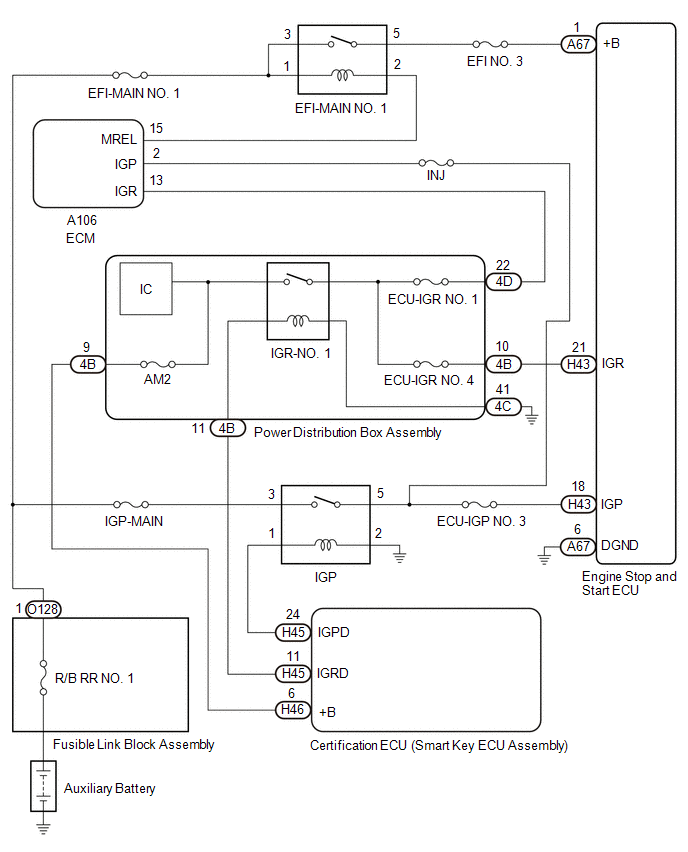
WIRING DIAGRAM
CAUTION / NOTICE / HINT
NOTICE:
-
Before replacing the engine stop and start ECU, read the number of starter operations and write it into a new engine stop and start ECU.
Click here

-
After replacing the engine stop and start ECU, perform learning of the external backup boost converter (eco run vehicle converter assembly).
Click here

-
After replacing the engine stop and start ECU or air conditioning amplifier assembly, reset and perform learning of the air conditioning information in the engine stop and start ECU.
Click here

-
When the ECM is replaced on a vehicle with a non-specified auxiliary battery, it is necessary to perform auxiliary battery type switching.
Click here

- Inspect the fuses for circuits related to this system before performing the following procedure.
HINT:
-
Using the GTS, read the freeze frame data before troubleshooting. System condition information is recorded as freeze frame data the moment a DTC is stored. This information can be useful when troubleshooting.
Click here

-
For wire harness and connector inspection procedures and precautions, refer to "
 "
"
-
DTCs for the stop and start system are not cleared even if the malfunction has been repaired. After repairing the malfunction, be sure to clear the DTCs.
Click here

PROCEDURE
| 1. | READ VALUE USING GTS (IG SWITCH) |
| Tester Display |
|---|
| IG Switch |
(a) Read the value displayed on the GTS.
| Tester Display | Result | Proceed to |
|---|---|---|
| IG Switch | ON | A |
| IG Switch | OFF | B |
| A |
 | USE SIMULATION METHOD TO CHECK |
|

| 2. | CHECK ENGINE STOP AND START ECU (IGP TERMINAL VOLTAGE) |
| *a | Component with harness connected (Engine Stop and Start ECU) | - | - |
(a) Turn the ignition switch to ON.
(b) Measure the voltage according to the value(s) in the table below.
Standard Voltage:
| Tester Connection | Switch Condition | Specified Condition |
|---|---|---|
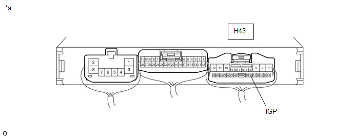
| H43-18 (IGP) - Body ground | Ignition switch ON | 9.5 to 14 V |
| NG |
 | GO TO STEP 8 |
|

| 3. | CHECK ENGINE STOP AND START ECU (+B TERMINAL VOLTAGE) |
| *a | Component with harness connected (Engine Stop and Start ECU) | - | - |
(a) Turn the ignition switch to ON.
(b) Measure the voltage according to the value(s) in the table below.
Standard Voltage:
| Tester Connection | Switch Condition | Specified Condition |
|---|---|---|
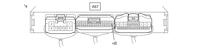
| A67-1 (+B) - Body ground | Ignition switch ON | 9.5 to 14 V |
| OK |
 | REPLACE ENGINE STOP AND START ECU |
|

| 4. | CHECK HARNESS AND CONNECTOR (ENGINE STOP AND START ECU - EFI-MAIN NO. 1 RELAY) |
(a) Disconnect the A67 engine stop and start ECU connector.
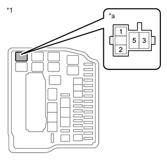
(b) Remove the EFI-MAIN NO. 1 relay from the No. 1 engine room relay block.
(c) Measure the resistance according to the value(s) in the table below.
Click here

Standard Resistance:
| Tester Connection | Condition | Specified Condition |
|---|---|---|
| A67-1 (+B) - 5 (EFI-MAIN NO. 1 relay holder) | Always | Below 1 Ω |
| A67-1 (+B) - Body ground and other terminals | Always | 10 kΩ or higher |
| 5 (EFI-MAIN NO. 1 relay holder) - Body ground and other terminals | Always | 10 kΩ or higher |
| NG |
 | REPAIR OR REPLACE HARNESS OR CONNECTOR |
|

| 5. | INSPECT POWER DISTRIBUTION BOX ASSEMBLY (EFI-MAIN NO. 1 RELAY) |
Click here

| NG |
 | REPLACE EFI-MAIN NO. 1 RELAY |
|

| 6. | CHECK HARNESS AND CONNECTOR (EFI-MAIN NO. 1 RELAY - ECM) |
(a) Remove the EFI-MAIN NO. 1 relay from the No. 1 engine room relay block.
(b) Measure the resistance according to the value(s) in the table below.
Standard Voltage:
| Tester Connection | Condition | Specified Condition |
|---|---|---|
| 2 (EFI-MAIN NO. 1 relay holder) - A106-15 (MREL) | Always | Below 1 Ω |
| NG |
 | REPAIR OR REPLACE HARNESS OR CONNECTOR |
|

| 7. | CHECK HARNESS AND CONNECTOR (EFI-MAIN NO. 1 RELAY - POWER SOURCE) |
| (a) Remove the EFI-MAIN NO. 1 relay from the No. 1 engine room relay block. |
|
(b) Measure the voltage according to the value(s) in the table below.
Standard Voltage:
| Tester Connection | Condition | Specified Condition |
|---|---|---|
| 1 (EFI-MAIN NO. 1 relay holder) - Body ground | Always | 9.5 to 14 V |
| 3 (EFI-MAIN NO. 1 relay holder) - Body ground | Always | 9.5 to 14 V |
| OK |
 | GO TO ECM POWER SOURCE CIRCUIT |
| NG |
 | REPAIR OR REPLACE HARNESS OR CONNECTOR |
| 8. | CHECK HARNESS AND CONNECTOR (ENGINE STOP AND START ECU - POWER DISTRIBUTION BOX ASSEMBLY (IGR-NO. 1 RELAY)) |
(a) Disconnect the H43 engine stop and start ECU connector.
(b) Disconnect the 4B power distribution box assembly connector.
(c) Measure the resistance according to the value(s) in the table below.
Standard Resistance:
| Tester Connection | Condition | Specified Condition |
|---|---|---|
| H43-21 (IGR) - 4B-10 | Always | Below 1 Ω |
| H43-21 (IGR) - Body ground and other terminals | Always | 10 kΩ or higher |
| 4B-10 - Body ground and other terminals | Always | 10 kΩ or higher |
| OK |
 | GO TO ENTRY AND START SYSTEM |
| NG |
 | REPAIR OR REPLACE HARNESS OR CONNECTOR |
 Starter Circuit Stuck On (P16449E)
DESCRIPTION The engine stop and start ECU detects abnormalities in the DI (+B) value that is input from the integrated IC (stop and start backup boost converter integrated IC) to the CPU...
 Backup Boost Converter Circuit Board(Thermistor) Signal Compare Failure (P30DF62,P30EF4B,P323A00,P323A16,P323AA2,P323B29,P323B38)
DESCRIPTION Refer to DTC P323A19. Click here
DTC No. Detection Item DTC Detection Condition Trouble Area Warning Indicate Memory Note P30DF62 Backup Boost Converter Circuit Board(Thermistor) Signal Compare Failure The following conditions is met for 1 second or more (1 trip detection logic):
Difference in temperature between thermistor 1 and thermistor 2 of the engine stop and start ECU is 40°C (72°F) or higher...
Other information:
Toyota Yaris XP210 (2020-2026) Reapir and Service Manual: Linear Solenoid Power Supply System Circuit Voltage Out of Range (C120C1C)
DESCRIPTION When a malfunction has occurred in the linear solenoid power source system, the AWD ECU assembly stores DTC C120C1C. DTC No. Detection Item DTC Detection Condition Trouble Area Warning Indicate Memory C120C1C Linear Solenoid Power Supply System Circuit Voltage Out of Range When the IG1 terminal voltage is 9...
Toyota Yaris XP210 (2020-2026) Reapir and Service Manual: Brake Switch "A" Circuit Open (P057113)
DESCRIPTION The skid control ECU (brake actuator assembly) detects the brake operating conditions through a signal transmitted by the stop light switch. The skid control ECU incorporates a circuit to detect an open circuit. This DTC is output when an open circuit is detected in the stop light signal input line...
Categories
- Manuals Home
- Toyota Yaris Owners Manual
- Toyota Yaris Service Manual
- Key Battery Replacement
- Headlights
- Engine Start Function When Key Battery is Dead
- New on site
- Most important about car
Keys

To use the auxiliary key, press the knob and pull out the auxiliary key from the smart key.
