Toyota Yaris: Fuel Injector (for Direct Injection) / Components
COMPONENTS
ILLUSTRATION
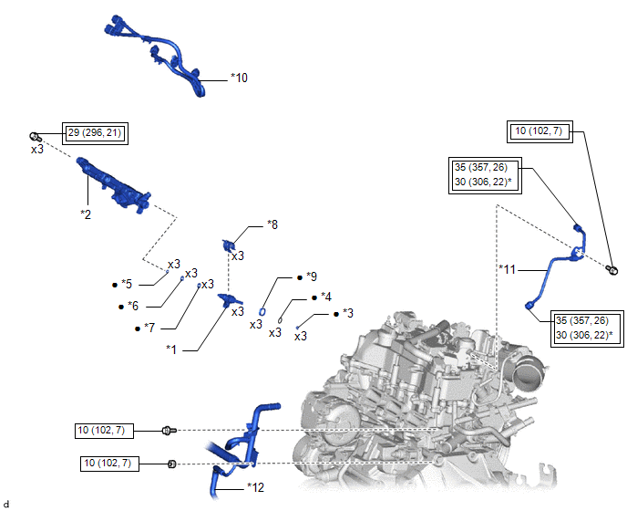
| *1 | FUEL INJECTOR ASSEMBLY | *2 | FUEL DELIVERY PIPE |
| *3 | FUEL INJECTOR SEAL | *4 | C-RING |
| *5 | NO. 3 FUEL INJECTOR BACK-UP RING | *6 | O-RING |
| *7 | NO. 1 FUEL INJECTOR BACK-UP RING | *8 | NOZZLE HOLDER CLAMP |
| *9 | INJECTOR VIBRATION INSULATOR | *10 | NO. 6 ENGINE WIRE |
| *11 | NO. 1 FUEL PIPE SUB-ASSEMBLY | *12 | NO. 2 WATER BY-PASS PIPE |
 | Tightening torque for "Major areas involving basic vehicle performance such as moving/turning/stopping": N*m (kgf*cm, ft.*lbf) |
 | N*m (kgf*cm, ft.*lbf): Specified torque |
| * | For use with SST | ● | Non-reusable part |

 Removal
REMOVAL CAUTION / NOTICE / HINT The necessary procedures (adjustment, calibration, initialization or registration) that must be performed after parts are removed and installed, or replaced during fuel injector assembly removal/installation are shown below...
Other information:
Toyota Yaris XP210 (2020-2026) Reapir and Service Manual: Inspection
INSPECTION PROCEDURE 1. INSPECT FOG LIGHT ASSEMBLY LH (a) Check that the fog light assembly LH. (1) Apply auxiliary battery voltage to the fog light assembly LH and check that the light comes on. OK: Condition Specified Condition A104-2 (B) - Auxiliary battery positive (+) A104-1 (E) - Auxiliary battery negative (-) Fog light assembly LH comes on If the result is not as specified, replace the fog light assembly LH...
Toyota Yaris XP210 (2020-2026) Reapir and Service Manual: Lost Communication with Alternator Missing Message (P161A87)
DESCRIPTION The ECM communicates with the generator assembly via LIN communication. If a LIN communication error is detected, the ECM stores this DTC. DTC No. Detection Item DTC Detection Condition Trouble Area MIL Note P161A87 Lost Communication with Alternator Missing Message Generator assembly or ECM communication stops for approximately 17 minutes or more with the ignition switch ON (1 trip detection logic) Wire harness or connector Generator assembly ECM Comes on SAE Code: P161A WIRING DIAGRAM CAUTION / NOTICE / HINT NOTICE: Inspect the fuses for circuits related to this system before performing the following inspection procedure...
Categories
- Manuals Home
- Toyota Yaris Owners Manual
- Toyota Yaris Service Manual
- Engine & Hybrid System
- Adjustment
- G16e-gts (engine Mechanical)
- New on site
- Most important about car
Fuel Gauge
The fuel gauge shows approximately how much fuel is remaining in the tank when the ignition is switched ON. We recommend keeping the tank over 1/4 full.

Copyright © 2026 www.toyaris4.com