Toyota Yaris: Fuel Injector (for Direct Injection) / Inspection
INSPECTION
PROCEDURE
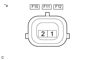
1. INSPECT FUEL INJECTOR ASSEMBLY
NOTICE:
This inspection is for checking the fuel injector assembly for an open or short. Because the fuel injector assembly of this vehicle is a high-pressure type, fuel injection volume cannot be checked.
| (a) Measure the resistance according to the value(s) in the table below. Standard Resistance:
If the result is not as specified, replace the fuel injector assembly. |
|
 Removal
REMOVAL CAUTION / NOTICE / HINT The necessary procedures (adjustment, calibration, initialization or registration) that must be performed after parts are removed and installed, or replaced during fuel injector assembly removal/installation are shown below...
 Installation
INSTALLATION CAUTION / NOTICE / HINT NOTICE: This procedure includes the installation of small-head bolts. Refer to Small-Head Bolts of Basic Repair Hint to identify the small-head bolts...
Other information:
Toyota Yaris XP210 (2020-2026) Reapir and Service Manual: Left Rear Wheel Speed Sensor Supply Voltage Circuit Short to Ground or Open (C14E614,C14E914)
DESCRIPTION Refer to DTC C050C1F. Click here DTC No. Detection Item DTC Detection Condition Trouble Area DTC Output from C14E614 Left Rear Wheel Speed Sensor Supply Voltage Circuit Short to Ground or Open With the +BS terminal voltage 9...
Toyota Yaris XP210 (2020-2026) Owner's Manual: Hill Launch Assist (HLA)(If equipped)
Hill Launch Assist (HLA) is a function which assists the driver in accelerating from a stop while on a slope. When the driver releases the brake pedal and depresses the accelerator pedal while on a slope, the function prevents the vehicle from rolling...
Categories
- Manuals Home
- Toyota Yaris Owners Manual
- Toyota Yaris Service Manual
- Battery Monitor Module General Electrical Failure (P058A01)
- Brake System Control Module "A" System Voltage System Voltage Low (C137BA2)
- Diagnostic Trouble Code Chart
- New on site
- Most important about car
Supplemental Restraint System (SRS) Precautions
The front and side supplemental restraint systems (SRS) include different types of air bags. Please verify the different types of air bags which are equipped on your vehicle by locating the “SRS AIRBAG” location indicators. These indicators are visible in the area where the air bags are installed.
The air bags are installed in the following locations:
The steering wheel hub (driver air bag) The front passenger dashboard (front passenger air bag) The outboard sides of the front seatbacks (side air bags) The front and rear window pillars, and the roof edge along both sides (curtain air bags)