Toyota Yaris: Fuel Injector (for Direct Injection) / Installation
INSTALLATION
CAUTION / NOTICE / HINT
NOTICE:
This procedure includes the installation of small-head bolts. Refer to Small-Head Bolts of Basic Repair Hint to identify the small-head bolts.
Click here

PROCEDURE
1. INSTALL FUEL INJECTOR SEAL
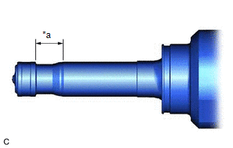
| (a) Apply engine conditioner to the area shown in the illustration. Using a piece of cloth, clean carbon deposits from the fuel injector assembly and its grooves. NOTICE:
|
|
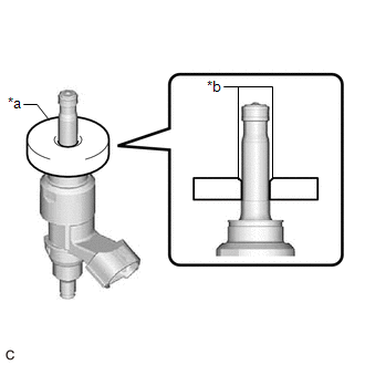
| (b) Apply engine oil to the fuel injector assembly contact surface of SST (guide), then attach SST (guide) to the fuel injector assembly with the chamfer facing the tip of the fuel injector assembly as shown in the illustration. SST: 09260-39030 09261-03030 |
|
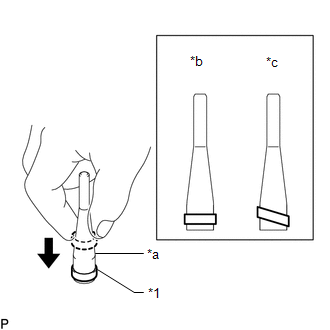
| (c) Install a new fuel injector seal to SST (holder). SST: 09260-39030 09261-03011 NOTICE: Be careful not to install the fuel injector seal to SST (holder) at an angle. Doing so will stretch the fuel injector seal. |
|
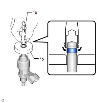
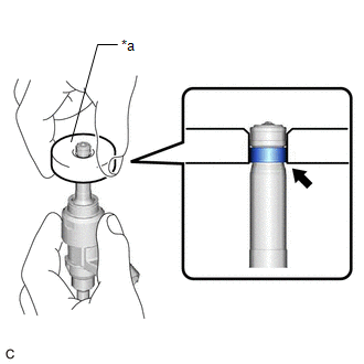
| (d) Install SST (holder) with the fuel injector seal to the tip of the fuel injector assembly. Slide the fuel injector seal downward into the fuel injector assembly groove with your fingers as shown in the illustration. SST: 09260-39030 09261-03011 09261-03030 HINT: Check that the fuel injector seal is seated in the fuel injector assembly groove as shown in the illustration. |
|
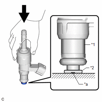
| (e) Slowly slide SST (guide) toward the tip of the fuel injector assembly. When the fuel injector assembly contact surface of SST (guide) aligns with the fuel injector seal as shown in the illustration, hold the position for 5 seconds or more to fully seat the fuel injector seal into the fuel injector assembly groove. SST: 09260-39030 09261-03030 NOTICE: Make sure the fuel injector seal is not pinched between SST (guide) and the edge of the fuel injector assembly groove. Replace the fuel injector seal if it becomes damaged. HINT:
|
|
| (f) After installing the fuel injector seals, check that they are not scratched, deformed or protruding from the fuel injector assembly groove. NOTICE: If a fuel injector seal is scratched, deformed or protruding from the groove, replace it with a new one. HINT: Use the same procedure to install the other fuel injector seals. |
|
2. INSTALL DIRECT FUEL INJECTOR ASSEMBLY
HINT:
Perform "Inspection After Repair" after replacing a fuel injector assembly.
Click here

| (a) Install a new injector vibration insulator and C-ring to each fuel injector assembly. NOTICE:
|
|
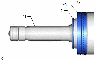
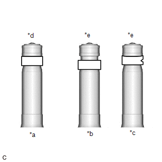
(b) Install a new O-ring and No. 1 fuel injector back-up ring to each fuel injector assembly as shown in the illustration.
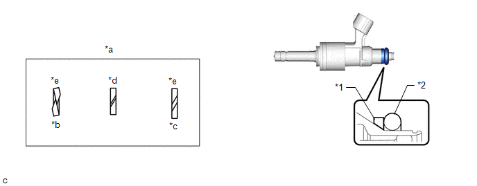
| *1 | No. 1 Fuel Injector Back-up Ring | *2 | O-ring |
| *a | No. 1 Fuel Injector Back-up Ring Opening | *b | Overlapped |
| *c | Stretched | *d | Correct |
| *e | Incorrect | - | - |
NOTICE:
- Check that there is no foreign matter or damage on the O-ring groove of the fuel injector assembly.
- Make sure that the No. 1 fuel injector back-up ring is installed in the correct orientation.
- Make sure that the No. 1 fuel injector back-up ring and O-ring are installed in the correct order.
- Check that the opening of the No. 1 fuel injector back-up ring is not overlapped or stretched as shown in the illustration.
- After installing the O-ring, check that it is not contaminated with foreign matter and is not damaged.
| (c) With the notch of a new No. 3 fuel injector back-up ring facing downward, install the No. 3 fuel injector back-up ring to each fuel injector assembly as shown in the illustration. NOTICE:
|
|
(d) Install the nozzle holder clamp to each fuel injector assembly.
(e) Align the protrusion of the nozzle holder clamp with the positioning hole of the fuel delivery pipe and insert the fuel injector assembly.
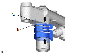
| *a | Protrusion |
| *b | Positioning Hole |
 | No Gap |
NOTICE:
- Make sure that there is no foreign matter or damage inside the fuel injector assembly installation holes (fuel delivery pipe).
- Do not allow gasoline to get on the O-rings or inside the installation holes.
- If it is difficult to insert the fuel injector assembly, apply new engine oil to the chamfer of the fuel injector assembly installation hole of the fuel delivery pipe. Be careful not to allow the fuel injector assembly to fall out of the fuel delivery pipe.
- Do not tilt the fuel injector assembly when inserting it into the fuel delivery pipe.
- Check that there is no gap between the fuel delivery pipe and the nozzle holder clamp.
-
Make sure the 3 fuel injector assemblies have the same flow classification number and that the flow classification number is 1, 2, 3, 4, 5, 6, 7, 8 or 9.
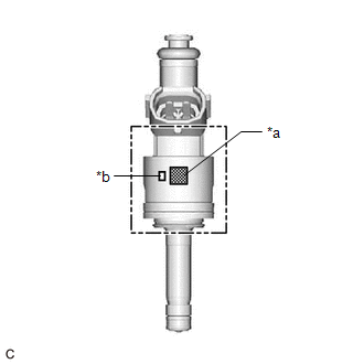
*a
QR Code
*b
Flow Classification Number
3. INSTALL NO. 6 ENGINE WIRE
(a) Connect the 3 fuel injector assembly connectors and install the No. 6 engine wire to the fuel delivery pipe.
(b) Engage the 2 clamps.
4. INSTALL FUEL DELIVERY PIPE
NOTICE:
When replacing the fuel delivery pipe, it is necessary to replace the No. 1 fuel pipe sub-assembly with a new one.
(a) Apply lubricant to the fuel injector assembly installation holes of the cylinder head sub-assembly.
(b) Temporarily install the fuel delivery pipe to the cylinder head sub-assembly.
NOTICE:
- If a fuel injector assembly is dropped or the tip of a fuel injector assembly is struck, replace it with a new one.
- Check that there is no foreign matter or damage on the fuel injector assembly installation holes of the cylinder head sub-assembly.
- When installing the fuel delivery pipe, push it in evenly without tilting it.
(c) Temporarily install the 4 bolts.
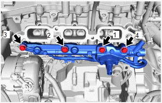
| (d) Install the fuel delivery pipe by uniformly tightening the 4 bolts in the order shown in the illustration. Torque: 29 N·m {296 kgf·cm, 21 ft·lbf} |
|
5. INSTALL NO. 2 WATER BY-PASS PIPE
(a) Install the No. 2 water by-pass pipe with the 2 bolts.
Torque:
10 N·m {102 kgf·cm}
6. INSTALL NO. 1 FUEL PIPE SUB-ASSEMBLY
Click here

7. INSTALL INTAKE MANIFOLD
Click here

8. CONNECT CABLE TO NEGATIVE AUXILIARY BATTERY TERMINAL
Click here

9. INITIALIZATION AFTER RECONNECTING AUXILIARY BATTERY TERMINAL
HINT:
When disconnecting and reconnecting the auxiliary battery, there is an automatic learning function that completes learning when the respective system is used.
Click here

10. INSPECT FOR FUEL LEAK
Click here

11. PERFORM INITIALIZATION
(a) Perform "Inspection After Repair" after replacing a fuel injector assembly.
Click here

 Inspection
INSPECTION PROCEDURE 1. INSPECT FUEL INJECTOR ASSEMBLY NOTICE: This inspection is for checking the fuel injector assembly for an open or short. Because the fuel injector assembly of this vehicle is a high-pressure type, fuel injection volume cannot be checked...

Other information:
Toyota Yaris XP210 (2020-2026) Reapir and Service Manual: Vehicle Control History
VEHICLE CONTROL HISTORY DESCRIPTION Vehicle Control History is a function that captures and stores ECU data when triggered by specific vehicle behavior. It may be possible to determine the cause of the malfunction by checking the vehicle history information and freeze frame data...
Toyota Yaris XP210 (2020-2026) Reapir and Service Manual: Installation
INSTALLATION PROCEDURE 1. INSTALL NO. 2 EQUALIZER STEREO COMPONENT BRACKET (a) Engage the guides to install the No. 2 equalizer stereo component bracket. (b) Install the 2 bolts. Torque: 4.5 N·m {46 kgf·cm, 40 in·lbf} 2. INSTALL NO...
Categories
- Manuals Home
- Toyota Yaris Owners Manual
- Toyota Yaris Service Manual
- Key Battery Replacement
- Removal
- Brake System Control Module "A" System Voltage System Voltage Low (C137BA2)
- New on site
- Most important about car
Turning the Engine Off
Stop the vehicle completely. Manual transaxle: Shift into neutral and set the parking brake.Automatic transaxle: Shift the selector lever to the P position and set the parking brake.
Press the push button start to turn off the engine. The ignition position is off.