Toyota Yaris: Lighting System / High Beam Headlight Circuit
DESCRIPTION
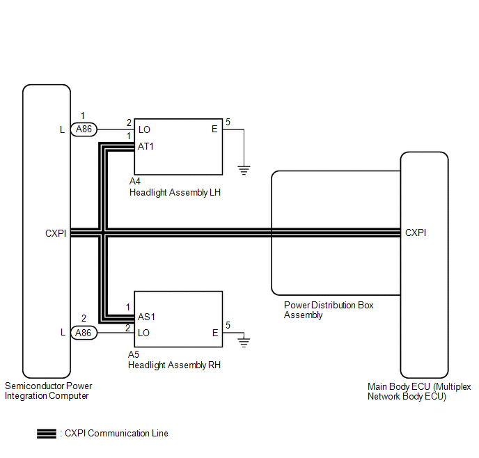
The main body ECU (multiplex network body ECU) controls the high beam headlights.
WIRING DIAGRAM
CAUTION / NOTICE / HINT
NOTICE:
-
Before replacing the main body ECU (multiplex network body ECU), refer to Registration.
Click here
.gif)
-
Check the operation of the low beam headlights. If the low beam headlights do not operate normally, refer to Problem Symptoms Table.
Click here
-
First perform the communication function inspections in How to Proceed with Troubleshooting to confirm that there are no CAN communication malfunctions before troubleshooting this symptom.
Click here
-
First perform the communication function inspections in How to Proceed with Troubleshooting to confirm that there are no CXPI communication malfunctions before troubleshooting this symptom.
Click here
PROCEDURE
| 1. | PERFORM ACTIVE TEST USING GTS |
(a) Enter the following menus: Body Electrical / Main Body / Active Test.
(b) Perform the Active Test according to the display on the GTS.
Body Electrical > Main Body > Active Test| Tester Display | Measurement Item | Control Range | Diagnostic Note |
|---|---|---|---|
| High Beam Headlight | High beam headlights | OFF or ON | - |
| Tester Display |
|---|
| High Beam Headlight |
OK:
High beam headlights illuminate.
| Result | Proceed to |
|---|---|
| OK | A |
| NG (LH side high beam light does not illuminate.) | B |
| NG (RH side high beam light does not illuminate.) | C |
| A |
.gif) | PROCEED TO NEXT SUSPECTED AREA SHOWN IN PROBLEM SYMPTOMS TABLE |
| C |
| GO TO STEP 5 |
|
.gif)
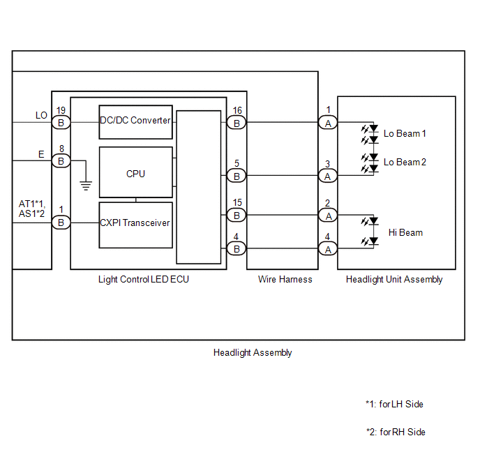
| 2. | CHECK HARNESS AND CONNECTOR (HEADLIGHT UNIT ASSEMBLY LH - LIGHT CONTROL LED ECU LH) |
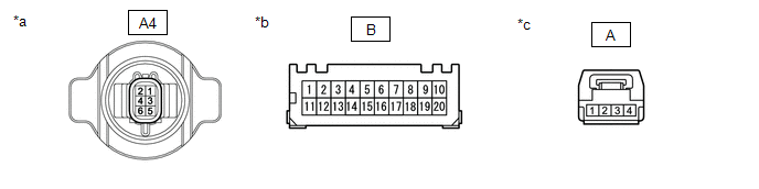
| *a | Component without harness connected (to Wire Harness) | *b | Component without harness connected (to Light Control LED ECU) |
| *c | Component without harness connected (to Headlight Unit Assembly LH) | - | - |
(a) Remove the headlight assembly LH.
Click here
(b) Remove the wire harness.
Click here
(c) Measure the resistance according to the value(s) in the table below.
Standard Resistance:
| Tester Connection | Condition | Specified Condition |
|---|---|---|
| A-[2] - B-[15] | Always | Below 1 Ω |
| A-[4] - B-[4] | Always | Below 1 Ω |
| A4-2 (LO) - B-[19] | Always | Below 1 Ω |
| A4-5 (E) - B-[8] | Always | Below 1 Ω |
| NG |
| REPAIR OR REPLACE HARNESS OR CONNECTOR |
|
| 3. | CHECK LIGHT CONTROL LED ECU LH |
(a) Interchange the light control LED ECU LH with RH and connect the connectors to them.
Click here
|
| 4. | CHECK OPERATION (HIGH BEAM HEADLIGHT) |
(a) Check that the low beam headlight operates normally.
OK:
High beam headlight operates normally.
| OK |
| REPLACE LIGHT CONTROL LED ECU LH |
| NG |
| REPLACE HEADLIGHT UNIT ASSEMBLY LH |
| 5. | CHECK HARNESS AND CONNECTOR (HEADLIGHT ASSEMBLY RH - LIGHT CONTROL ECU) |
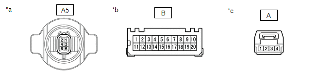
| *a | Component without harness connected (to Wire Harness) | *b | Component without harness connected (to Light Control ECU) |
| *c | Component without harness connected (to Headlight Unit Assembly RH) | - | - |
(a) Remove the headlight assembly RH.
Click here
(b) Remove the wire harness.
Click here
(c) Measure the resistance according to the value(s) in the table below.
Standard Resistance:
| Tester Connection | Condition | Specified Condition |
|---|---|---|
| A-[2] - B-[15] | Always | Below 1 Ω |
| A-[4] - B-[4] | Always | Below 1 Ω |
| A5-2 (LO) - B-[19] | Always | Below 1 Ω |
| A5-5 (E) - B-[8] | Always | Below 1 Ω |
| NG |
| REPAIR OR REPLACE HARNESS OR CONNECTOR |
|
| 6. | CHECK LIGHT CONTROL LED ECU RH |
(a) Interchange the light control LED ECU RH with LH and connect the connectors to them.
Click here
|
| 7. | CHECK OPERATION (HIGH BEAM HEADLIGHT) |
(a) Check that the low beam headlight operates normally.
OK:
High beam headlight operates normally.
| OK |
| REPLACE LIGHT CONTROL LED ECU RH |
| NG |
| REPLACE HEADLIGHT UNIT ASSEMBLY RH |
 Taillight Relay Circuit
DESCRIPTION The main body ECU (multiplex network body ECU) controls the, taillight and license plate light. WIRING DIAGRAM
CAUTION / NOTICE / HINT NOTICE:
First perform the communication function inspections in How to Proceed with Troubleshooting to confirm that there are no CAN communication malfunctions before troubleshooting this symptom...

Other information:
Toyota Yaris XP210 (2020-2026) Owner's Manual: Essential Information Introduction
Be careful not to hurt yourself when inspecting your vehicle, replacing a tire, or doing some kind of maintenance such as car washing. In particular, wear thick work gloves such as cotton gloves when touching areas that are difficult to see while inspecting or working on your vehicle...
Toyota Yaris XP210 (2020-2026) Reapir and Service Manual: STA Signal Circuit
DESCRIPTION While the engine is being cranked, a starter operation request signal is sent to terminal STA of the ECM. HINT: If there is an open in the STA circuit of the ECM, stop and start control will be prohibited after the third time the engine is started by stop and start control...
Categories
- Manuals Home
- Toyota Yaris Owners Manual
- Toyota Yaris Service Manual
- Maintenance
- Engine Start Function When Key Battery is Dead
- How to connect USB port/Auxiliary jack
- New on site
- Most important about car
Keys

To use the auxiliary key, press the knob and pull out the auxiliary key from the smart key.
