Toyota Yaris: Sfi System / Fuel Pump Control General Electrical Failure (P12D501)
DESCRIPTION
Refer to DTC P062712.
Click here

| DTC No. | Detection Item | DTC Detection Condition | Trouble Area | MIL | Note |
|---|---|---|---|---|---|
| P12D501 | Fuel Pump Control General Electrical Failure | When the fuel pump control ECU operation duty ratio is 3 to 65%, the fuel pump control ECU detects a short in the fuel pump circuit for 3 seconds or more (1 trip detection logic). |
| - | SAE: P12D5 |
| DTC No. | Data List |
|---|---|
| P12D501 | Fuel Pump Control Duty Ratio |
MONITOR DESCRIPTION
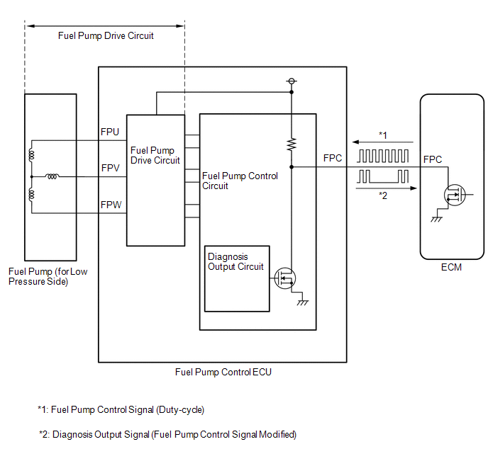
The fuel pump control ECU monitors the fuel pump drive circuit.
When a malfunction is detected in the fuel pump drive circuit, the diagnosis output circuit in the fuel pump control ECU modifies the operation signal sent by the ECM to indicate that there is a malfunction.
When the fuel pump control ECU operation duty ratio is 3 to 65%, and short in the fuel pump circuit is detected for 3 seconds or more, the diagnosis output circuit in the fuel pump control ECU modifies the operation signal sent by the ECM to indicate that there is a malfunction and the ECM stores a DTC.
MONITOR STRATEGY
| Required Sensors/Components | Fuel pump control ECU |
| Frequency of Operation | Continuous |
CONFIRMATION DRIVING PATTERN
- Connect the GTS to the DLC3.
- Turn the ignition switch to ON.
- Turn the GTS on.
- Clear the DTCs (even if no DTCs are stored, perform the clear DTC procedure).
- Turn the ignition switch off and wait for at least 30 seconds.
- Turn the ignition switch to ON.
- Turn the GTS on.
- Start the engine and wait 10 seconds or more.
- Enter the following menus: Powertrain / Engine / Trouble Codes.
-
Read the pending DTCs.
HINT:
- If a pending DTC is output, the system is malfunctioning.
- If a pending DTC is not output, perform the following procedure.
- Enter the following menus: Powertrain / Engine / Utility / All Readiness.
- Input the DTC: P12D501.
-
Check the DTC judgment result.
GTS Display
Description
NORMAL
- DTC judgment completed
- System normal
ABNORMAL
- DTC judgment completed
- System abnormal
INCOMPLETE
- DTC judgment not completed
- Perform driving pattern after confirming DTC enabling conditions
HINT:
- If the judgment result is NORMAL, the system is normal.
- If the judgment result is ABNORMAL, the system is malfunctioning.
- If the judgment result is INCOMPLETE, run the engine at an engine speed of 2500 rpm or more for 10 seconds or more and check the DTC judgment result again.
WIRING DIAGRAM
Refer to DTC P062712.
Click here

CAUTION / NOTICE / HINT
HINT:
Read Freeze Frame Data using the GTS. The ECM records vehicle and driving condition information as Freeze Frame Data the moment a DTC is stored. When troubleshooting, Freeze Frame Data can help determine if the vehicle was moving or stationary, if the engine was warmed up or not, if the air fuel ratio was lean or rich, and other data from the time the malfunction occurred.
PROCEDURE
| 1. | INSPECT FUEL PUMP CONTROL ECU |
(a) Disconnect the fuel pump control ECU connector.
(b) Measure the resistance according to the value(s) in the table below.
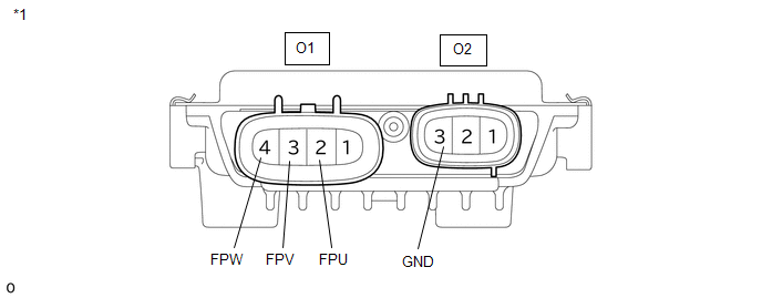
| *1 | Fuel Pump Control ECU | - | - |
Standard Resistance:
| Tester Connection | Condition | Specified Condition |
|---|---|---|
| O1-2 (FPU) - O2-3 (GND) | Always | 2 kΩ or higher |
| O1-3 (FPV) - O2-3 (GND) | Always | 2 kΩ or higher |
| O1-4 (FPW) - O2-3 (GND) | Always | 2 kΩ or higher |
HINT:
This procedure checks for an internal short of the fuel pump control ECU when its transistor is stuck on.
| NG |
 | REPLACE FUEL PUMP CONTROL ECU |
|

| 2. | PERFORM ACTIVE TEST USING GTS (FUEL PUMP SINGLE PHASE ENERGIZATION) |
(a) Disconnect the fuel pump control ECU connector.
(b) Operate the fuel pump control ECU using the Active Test function and measure the voltage according to the value(s) in the table below.
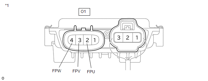
| *1 | Fuel Pump Control ECU | - | - |
| Tester Display |
|---|
| Fuel Pump Single Phase Energization |
Standard Voltage:
| Tester Connection | GTS Operation | Specified Condition |
|---|---|---|
| O1-2 (FPU) - Body ground | U Phase | 4.4 to 8.4 V* |
| O1-3 (FPV) - Body ground | U Phase | 8 to 15.5 V |
| O1-4 (FPW) - Body ground | U Phase | 8 to 15.5 V |
| O1-3 (FPV) - Body ground | V Phase | 4.4 to 8.4 V* |
| O1-2 (FPU) - Body ground | V Phase | 8 to 15.5 V |
| O1-4 (FPW) - Body ground | V Phase | 8 to 15.5 V |
| O1-4 (FPW) - Body ground | W Phase | 4.4 to 8.4 V* |
| O1-2 (FPU) - Body ground | W Phase | 8 to 15.5 V |
| O1-3 (FPV) - Body ground | W Phase | 8 to 15.5 V |
HINT:
- *: This Active Test limits the fuel pump control ECU output duty cycle to 50%. Therefore, the output voltage of the fuel pump control ECU will be approximately 50% of the power source voltage (+B terminal).
- Before performing this inspection, check that the auxiliary battery voltage is between 11 and 14 V (not depleted).
| NG |
 | REPLACE FUEL PUMP CONTROL ECU |
|

| 3. | CHECK HARNESS AND CONNECTOR (FUEL PUMP CONTROL ECU - FUEL PUMP (FOR LOW PRESSURE SIDE)) |
(a) Disconnect the fuel pump control ECU connector.
(b) Disconnect the fuel pump (for low pressure side) connector.
(c) Measure the resistance according to the value(s) in the table below.
Standard Resistance:
| Tester Connection | Condition | Specified Condition |
|---|---|---|
| O1-2 (FPU) or O21-3 (BLPU) - Body ground and other terminals | Always | 10 kΩ or higher |
| O1-3 (FPV) or O21-4 (BLPV) - Body ground and other terminals | Always | 10 kΩ or higher |
| O1-4 (FPW) or O21-2 (BLPW) - Body ground and other terminals | Always | 10 kΩ or higher |
| OK |
 | REPLACE FUEL PUMP (FOR LOW PRESSURE SIDE) |
| NG |
 | REPAIR OR REPLACE HARNESS OR CONNECTOR |
 Fuel Pump Control Circuit Current Out of Range (P12D41D)
DESCRIPTION Refer to DTC P062712. Click here
DTC No. Detection Item DTC Detection Condition Trouble Area MIL Note P12D41D Fuel Pump Control Circuit Current Out of Range When the fuel pump control ECU operation duty ratio is 3 to 65%, overcurrent in the fuel pump circuit is detected for 3 seconds or more (1 trip detection logic)...
 Pre-ignition Detected (P137800)
DESCRIPTION If sudden early ignition (pre-ignition) occurs continuously in a short period of time, a DTC is stored. This pre-ignition is a phenomenon inherent in boosted engines...
Other information:
Toyota Yaris XP210 (2020-2026) Reapir and Service Manual: Customize Parameters
CUSTOMIZE PARAMETERS CUSTOMIZE AIR CONDITIONING SYSTEM (a) Customizing with the GTS. NOTICE: When the customer requests a change in a function, first make sure that the function can be customized. Be sure to make a note of the current settings before customizing...
Toyota Yaris XP210 (2020-2026) Reapir and Service Manual: After Engine Stops due to Stop and Start System, Engine does not Restart
DESCRIPTION This is the troubleshooting procedure for situations where the engine does not restart after having been stopped by the stop and start system. For information on stop and start control, refer to the system description. Click here CAUTION / NOTICE / HINT PRECAUTIONS WHEN THE ENGINE STOP AND START ECU AND THE STARTER ASSEMBLY ARE REPLACED NOTICE: When the engine stop and start ECU is replaced, it is necessary to read the number of starter operations before replacement and store this number in the new engine stop and start ECU after replacement, and to perform external backup boost converter (eco run vehicle converter assembly) existence learning...
Categories
- Manuals Home
- Toyota Yaris Owners Manual
- Toyota Yaris Service Manual
- Maintenance
- Immobilizer System
- Engine & Hybrid System
- New on site
- Most important about car
Refueling
Before refueling, close all the doors, windows, and the liftgate/trunk lid, and switch the ignition OFF.
To open the fuel-filler lid, pull the remote fuel-filler lid release.
