Toyota Yaris: Charging System / Freeze Frame Data
FREEZE FRAME DATA
DESCRIPTION
The ECM records vehicle and driving condition information as freeze frame data the moment a DTC is stored. When troubleshooting, freeze frame data can be helpful in determining whether the vehicle was moving or stationary, whether the engine was warmed up or not, whether the air fuel ratio was lean or rich, as well as other data recorded at the time of a malfunction.
HINT:
- If it is impossible to reproduce the symptoms even though a DTC is stored, confirm the freeze frame data.
- Freeze frame data is available in long and short forms.
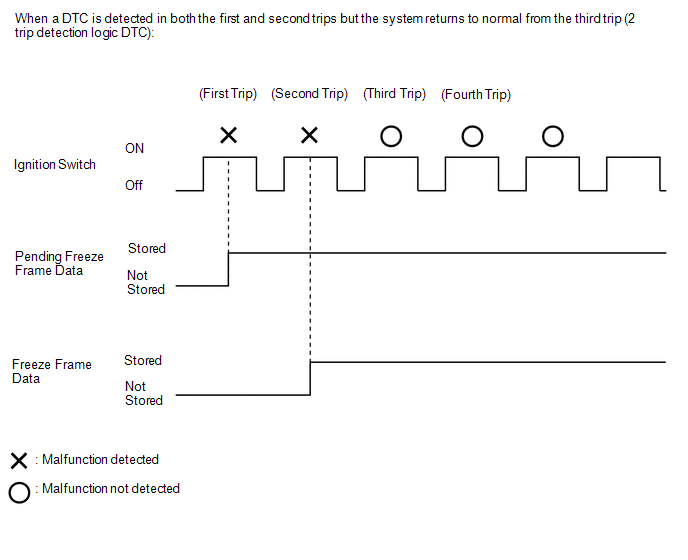
PENDING FREEZE FRAME DATA
HINT:
Pending freeze frame data is stored when a 2 trip DTC is first detected during the first trip.
(a) Connect the GTS to the DLC3.
(b) Turn the ignition switch to ON.
(c) Turn the GTS on.
(d) Enter the following menus: Powertrain / Engine / Trouble Codes.
(e) Select a DTC in order to display its pending freeze frame data.
HINT:
-
Pending freeze frame data is cleared when any of the following occurs:
- Using the GTS, the DTCs are cleared.
- The cable is disconnected from the negative (-) battery terminal.
- 40 trips with the engine fully warmed up have been performed after the condition returns to normal. (Pending freeze frame data will not be cleared only by the system returning to normal.)
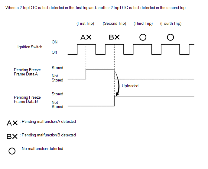
- With previous pending freeze frame data stored, if pending freeze frame data is newly stored when a 2 trip DTC is detected in the first trip, the old freeze frame data will be replaced with the new data of the newly detected DTC in the next trip.
LIST OF FREEZE FRAME DATA
(a) According to the display on the GTS, read the freeze frame data.
Powertrain > Engine| Tester Display |
|---|
| Battery Voltage |
| Battery Sensor Voltage |
| Alternator Output Duty Ratio |
| Status of Alternator Temperature High |
| Alternator Voltage - Non Active Test |
| Voltage of Alternator |
 Dtc Check / Clear
DTC CHECK / CLEAR CHECK DTC (a) Connect the GTS to the DLC3. (b) Turn the ignition switch to ON. (c) Turn the GTS on. (d) Enter the following menus: Powertrain / Engine / Trouble Codes...
 Fail-safe Chart
FAIL-SAFE CHART If any of the following DTCs are stored, the ECM enters fail-safe mode to allow the vehicle to be driven temporarily. DTC No. Fail-safe Operation Fail-safe Deactivation Condition P058A01 P062049 P065C07 P160200 P161A87 P162B87 Generator command is fixed...
Other information:
Toyota Yaris XP210 (2020-2026) Reapir and Service Manual: Inspection
INSPECTION PROCEDURE 1. INSPECT AIR CONDITIONING CONTROL ASSEMBLY (a) Check the illumination. (1) Apply auxiliary battery voltage to the air conditioning control assembly and check that the illumination. OK: Measurement Condition Specified Condition Auxiliary battery positive (+) → H31-8 (ILL+) Auxiliary battery negative (-) → H31-14 (ILL-) Illumination illuminates If the result is not as specified, replace the air conditioning control assembly...
Toyota Yaris XP210 (2020-2026) Reapir and Service Manual: High Mounted Stop Light Assembly
ComponentsCOMPONENTS ILLUSTRATION *1 CENTER STOP LIGHT ASSEMBLY - - RemovalREMOVAL PROCEDURE 1. REMOVE REAR SPOILER ASSEMBLY Click here 2. REMOVE CENTER STOP LIGHT ASSEMBLY (a) Remove the 2 screws to remove the center stop light assembly...
Categories
- Manuals Home
- Toyota Yaris Owners Manual
- Toyota Yaris Service Manual
- Key Battery Replacement
- Opening and Closing the Liftgate/Trunk Lid
- To Set Speed
- New on site
- Most important about car
Key Suspend Function
If a key is left in the vehicle, the functions of the key left in the vehicle are temporarily suspended to prevent theft of the vehicle.
To restore the functions, press the unlock button on the functions-suspended key in the vehicle.