Toyota Yaris: Sfi System / Freeze Frame Data
FREEZE FRAME DATA
DESCRIPTION
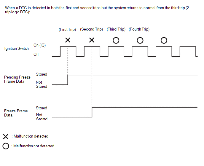
The ECM records vehicle and driving condition information as Freeze Frame Data the moment a DTC is stored. When troubleshooting, Freeze Frame Data can be helpful in determining whether the vehicle was moving or stationary, whether the engine was warmed up or not, whether the air fuel ratio was lean or rich, as well as other data recorded at the time of a malfunction.
HINT:
- If it is impossible to replicate the problem even though a DTC is detected, confirm the Freeze Frame Data.
- Freeze Frame Data is available in long and short forms.
PENDING FREEZE FRAME DATA
HINT:
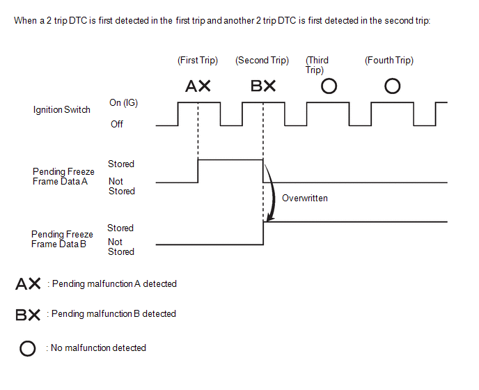
Pending Freeze Frame Data is stored when a 2 trip detection logic DTC is first detected during the first trip.
(a) Connect the GTS to the DLC3.
(b) Turn the ignition switch to ON.
(c) Turn the GTS on.
(d) Enter the following menus: Powertrain / Engine / Trouble Codes.
(e) Select a DTC in order to display its pending Freeze Frame Data.
Powertrain > Engine > Trouble CodesHINT:
-
Pending Freeze Frame Data is cleared when any of the following occurs.
- Using the GTS, the DTCs are cleared.
- The cable is disconnected from the negative (-) auxiliary battery terminal.
- 40 trips with the engine fully warmed up have been performed after returning to normal. (Pending Freeze Frame Data will not be cleared by only returning the system to normal.)
- With previous pending Freeze Frame Data stored, if pending Freeze Frame Data is newly stored when a 2 trip detection logic DTC is detected in the first trip, the old Freeze Frame Data will be replaced with a new data of the newly detected DTC in the next trip.
LIST OF FREEZE FRAME DATA
Powertrain > Engine| Tester Display |
|---|
| Total Distance Traveled |
| Total Distance Traveled - Unit |
| Vehicle Speed |
| Engine Speed |
| Calculate Load |
| Vehicle Load |
| Mass Air Flow Sensor |
| Atmospheric Pressure |
| Intake Manifold Absolute Pressure |
| Intake Manifold Absolute Pressure Supported |
| Engine Oil Temperature Sensor |
| Coolant Temperature |
| Intake Air Temperature |
| Intake Air Temperature B1S1 (Turbo) |
| Intake Air Temperature B1S1 (Turbo) Supported |
| Intake Air Temperature B1S2 (Turbo) |
| Intake Air Temperature B1S2 (Turbo) Supported |
| Ambient Temperature |
| Engine Run Time |
| IG-ON Coolant Temperature |
| Initial Engine Coolant Temperature |
| IG-ON Intake Air Temperature |
| Initial Engine Intake Air Temperature |
| Battery Voltage |
| Battery Sensor Voltage |
| BATT Voltage |
| IG2 / IGP |
| IGR |
| Glow Indicator Supported |
| Engine Oil Pressure |
| Accelerator Position |
| Accelerator Position Sensor No.1 Voltage % |
| Accelerator Position Sensor No.2 Voltage % |
| Accelerator Position Sensor No.1 Voltage |
| Accelerator Position Sensor No.2 Voltage |
| Accelerator Idle Position |
| Accelerator Position Sensor No.1 Fully Closed Learn Value |
| Accelerator Position Sensor No.2 Fully Closed Learn Value |
| Engine Starting Torque Control Count |
| Throttle Position Sensor No.1 Voltage % |
| Throttle Position Sensor No.2 Voltage % |
| System Guard |
| Open Side Malfunction |
| Throttle Request Position |
| Throttle Sensor Position |
| Throttle Position Sensor No.1 Voltage |
| Throttle Position Sensor No.2 Voltage |
| Throttle Position Command |
| Throttle Position Sensor Open Position No.1 |
| Throttle Position Sensor Open Position No.2 |
| Throttle Motor Current |
| Throttle Motor Duty Ratio |
| Throttle Motor Duty Ratio (Open) |
| Throttle Motor Duty Ratio (Close) |
| Throttle Position Sensor Fully Closed Learn Value |
| +BM Voltage |
| Actuator Power Supply |
| Throttle Air Flow Learn Value (Area 1) |
| Throttle Air Flow Learn Value (Area 2) |
| Throttle Air Flow Learn Value (Area 3) |
| Throttle Air Flow Learn Value (Calculated Value) |
| Throttle Air Flow Learn Value (Atmosphere Pressure Offset Value) |
| Turbocharger/Supercharger Inlet Pressure Bank1 |
| Low Revolution Control |
| Engine Stall Control F/B Flow |
| ISC F/B Learn Torque |
| ISC Total AUXS Torque |
| ISC F/B Torque |
| Sum of ISC F/B Torque (Recent) |
| ISC AUXS Torque (Alternator) |
| ISC AUXS Torque (Air Conditioner) |
| Throttle Air Flow F/B Value |
| Throttle Position |
| Target Fuel Pressure (High) |
| Target Fuel Pressure (High) Supported |
| Target Fuel Pressure (Low) / Target Fuel Pressure 2 |
| Target Fuel Pressure (Low) / Target Fuel Pressure 2 Supported |
| Fuel Pressure (High) |
| Fuel Pressure (High) Supported |
| Fuel Pressure (Low) / Fuel Pressure 2 |
| Fuel Pressure (Low) / Fuel Pressure 2 Supported |
| Fuel Pump Target Speed |
| Fuel Pump F/B Offset |
| Fuel Pump Control Duty Ratio |
| Low Pressure Fuel Delivery Internal Temperature |
| Injector Cylinder #1 (Port) |
| Injection Volume Cylinder #1 |
| Target Fuel Pressure Offset |
| Injection Volume |
| Low Fuel Pressure Sensor |
| High Fuel Pressure Sensor |
| High Pressure Fuel Pump Duty Ratio (D4) |
| High Pressure Fuel Pump Discharge Rate |
| High Pressure Fuel Pump Internal Temperature |
| Injection Mode |
| Injection Switching Status |
| Injection Timing Cylinder #1 (D4) |
| Injection Time Cylinder #1 (D4) |
| Current Fuel Type |
| EVAP (Purge) VSV |
| Target Air-Fuel Ratio |
| A/F (O2) Lambda Sensor B1S1 |
| A/F (O2) Lambda Sensor B1S2 |
| A/F (O2) Sensor Current B1S1 |
| A/F (O2) Sensor Current B1S2 |
| A/F (O2) Sensor Heater Duty Ratio B1S1 |
| A/F Sensor Heater Current Value B1S2 |
| A/F Sensor Heater Duty B1S2 |
| A/F Sensor Impedance B1S1 |
| A/F Sensor Impedance B1S2 |
| A/F (O2) Sensor +Terminal Voltage Bank 1 |
| A/F (O2) Sensor -Terminal Voltage Bank 1 |
| A/F (O2) Sensor Heater Control Duty Ratio Bank1 |
| A/F (O2) Sensor Heater Output Duty Ratio Bank1 |
| A/F (O2) Sensor Heater ON Current Value Bank1 |
| A/F (O2) Sensor Heater Current-Carrying Status Bank1 (at Heater OFF) |
| A/F (O2) Sensor Heater Overcurrent Bank1 |
| A/F (O2) Sensor Heater Control Run Time Bank1 |
| Short FT B1S1 |
| Short FT B1S2 |
| Long FT B1S1 |
| Long FT B1S2 |
| Total FT Bank 1 |
| Fuel System Status Bank 1 |
| Fuel System Status Bank 2 |
| Ignition Timing Cylinder #1 |
| Knock F/B Value |
| Knock Correct Learn Value |
| Idle Spark Advance Control Cylinder #1 |
| Idle Spark Advance Control Cylinder #2 |
| Idle Spark Advance Control Cylinder #3 |
| Mass Air Flow Circuit |
| VSV for AICS |
| VVT Advance Fail |
| Exhaust VVT Retarded Fail |
| Intake VVT Hold Learn Value Bank 1 |
| Intake VVT Change Angle Bank 1 |
| Intake VVT OCV Control Duty Ratio Bank 1 |
| Exhaust VVT Hold Learn Value Bank 1 |
| Exhaust VVT Change Angle Bank 1 |
| Exhaust VVT OCV Control Duty Ratio Bank 1 |
| Intake VVT Target Angle Bank 1 |
| Exhaust VVT Target Angle Bank 1 |
| Intake VVT Timing Most Over-Retarded Learn Value Bank 1 |
| Exhaust VVT Timing Most Over-Advanced Learn Value Bank 1 |
| Target Boost Pressure |
| Target Boost Pressure Supported |
| Target Boost Pressure2 Supported |
| Boost Pressure Sensor |
| Boost Pressure Sensor Supported |
| Boost Pressure Sensor2 Supported |
| Catalyst Temperature B1S1 |
| Catalyst Temperature B1S2 |
| Starter SW |
| Neutral Position SW |
| Shift SW Status (Neutral) Supported |
| Clutch SW |
| Stop Light SW |
| Immobiliser Communication |
| Cruise Main SW |
| Closed Throttle Position SW |
| TC Terminal |
| MIL ON Run Distance |
| Running Time from MIL ON |
| Time after DTC Cleared |
| Distance from DTC Cleared |
| Warmup Cycle Cleared DTC |
| Distance Traveled from Last Battery Cable Disconnect |
| IG OFF Elapsed Time |
| Soak IC Current Timer Value |
| Ignition Trigger Count |
| Misfire Count Cylinder #1 |
| Misfire Count Cylinder #2 |
| Misfire Count Cylinder #3 |
| All Cylinders Misfire Count |
| Misfire RPM |
| Misfire Load |
| Misfire Margin |
| Catalyst OT Misfire Fuel Cut |
| Catalyst OT Misfire Fuel Cut History |
| Catalyst OT Misfire Fuel Cut Cylinder #1 |
| Catalyst OT Misfire Fuel Cut Cylinder #2 |
| Catalyst OT Misfire Fuel Cut Cylinder #3 |
| A/F Learn Value Idle (Port) Bank 1 |
| A/F Learn Value Low (Port) Bank 1 |
| A/F Learn Value Mid No.1 (Port) Bank 1 |
| A/F Learn Value Mid No.2 (Port) Bank 1 |
| A/F Learn Value High (Port) Bank 1 |
| Engine Speed (Starter Off) |
| Starter Count |
| Run Distance of Previous Trip |
| Engine Starting Time |
| Engine Start Hesitation |
| Low Revolution for Engine Start |
| Fuel Cut Elapsed Time |
| Previous Trip Coolant Temp |
| Previous Trip Intake Temp |
| Engine Oil Temperature |
| Previous Trip Eng Oil Temp |
| Ambient Temp for A/C |
| Previous Trip Ambient Temp |
| A/F Learn Value Idle Bank 1 |
| A/F Learn Value Low Bank 1 |
| A/F Learn Value Mid No.1 Bank 1 |
| A/F Learn Value Mid No.2 Bank 1 |
| A/F Learn Value High Bank 1 |
| Engine ECU Internal Temperature |
| Battery Current |
| Battery Temperature |
| Alternator Output Duty Ratio |
| Status of Alternator Temperature High |
| Alternator Voltage - Non Active Test |
| Voltage of Alternator |
| Battery Charging Rate Accuracy |
| Battery Status of Full Charge |
| Cooling Fan Duty Ratio |
| Brake Override System |
| Immobiliser Fuel Cut Status |
| Immobiliser Fuel Cut History |
| Fuel Cut Condition |
| Idle Fuel Cut |
| TAU Fuel Cut |
| Electric Component Actuation Restriction Count |
| Key Unlock Signal |
| Engine Speed Cylinder #1 |
| Engine Speed Cylinder #2 |
| Engine Speed Cylinder #3 |
| Average Engine Speed of All Cylinder |
| NIM Sensor Speed |
| NIM Sensor Voltage |
| Shift SW Status (R Range) |
| Shift SW Status (N,P Range) |
| Shift SW Status (N,P Range) Supported |
| Clutch Stroke Position |
| Clutch Stroke Sensor Voltage |
| M/T Oil Temperature |
| Drive Mode Status |
| Mode Cancel SW |
| Power Mode SW |
| Track Mode Switch |
| iMT SW |
| iMT Telltale |
| Down Shift Indication |
| Up Shift Indication |
| Stop and Start System Engine Status |
| Air Bypass Valve Control |
 Check Mode Procedure
CHECK MODE PROCEDURE HINT: Compared to normal mode, check mode is more sensitive to malfunctions. Therefore, check mode can detect malfunctions that cannot be detected in normal mode...
 Fail-safe Chart
FAIL-SAFE CHART If any of the following DTCs are stored, the ECM enters fail-safe mode to allow the vehicle to be driven temporarily or stops fuel injection...
Other information:
Toyota Yaris XP210 (2020-2026) Reapir and Service Manual: Components
COMPONENTS ILLUSTRATION *1 SYMBOL EMBLEM *2 NO. 4 BACK DOOR NAME PLATE *3 NO. 2 BACK DOOR NAME PLATE - - ● Non-reusable part - - ILLUSTRATION *1 NO. 1 BACK DOOR NAME PLATE - - ● Non-reusable part - - ILLUSTRATION *A for LH side *B for RH side *1 NO...
Toyota Yaris XP210 (2020-2026) Reapir and Service Manual: Throttle Actuator "A" Control Throttle Body Range/Performance (P211900,P211904,P211977,P21199B)
DESCRIPTION The electronic throttle control system is composed of the throttle actuator, throttle position sensor, accelerator pedal position sensor, and ECM. The ECM operates the throttle actuator to regulate the throttle valve in response to driver inputs...
Categories
- Manuals Home
- Toyota Yaris Owners Manual
- Toyota Yaris Service Manual
- Brake System Control Module "A" System Voltage System Voltage Low (C137BA2)
- Opening and Closing the Liftgate/Trunk Lid
- Diagnostic Trouble Code Chart
- New on site
- Most important about car
Supplemental Restraint System (SRS) Precautions
The front and side supplemental restraint systems (SRS) include different types of air bags. Please verify the different types of air bags which are equipped on your vehicle by locating the “SRS AIRBAG” location indicators. These indicators are visible in the area where the air bags are installed.
The air bags are installed in the following locations:
The steering wheel hub (driver air bag) The front passenger dashboard (front passenger air bag) The outboard sides of the front seatbacks (side air bags) The front and rear window pillars, and the roof edge along both sides (curtain air bags)