Toyota Yaris: Sfi System / Check Mode Procedure
CHECK MODE PROCEDURE
HINT:
Compared to normal mode, check mode is more sensitive to malfunctions. Therefore, check mode can detect malfunctions that cannot be detected in normal mode.
NOTICE:
All of the stored DTCs and Freeze Frame Data are cleared if: 1) the ECM is changed from normal mode to check mode or vice versa; or 2) the ignition switch is turned from ON to ACC or off while in check mode. Before changing modes, always check for and note any DTCs and Freeze Frame Data.
CHECK MODE PROCEDURE
(a) Check and ensure the following conditions:
(1) Auxiliary battery voltage is 11 V or higher.
(2) Accelerator pedal fully released.
(3) Shift lever is in neutral.
(4) A/C switch is off.
(b) Turn the ignition switch off.
(c) Connect the GTS to the DLC3.
(d) Turn the ignition switch to ON.
(e) Turn the GTS on.
(f) Enter the following menus: Powertrain / Engine / Utility / Check Mode.
Powertrain > Engine > Utility| Tester Display |
|---|
| Check Mode |
(g) Change the ECM from normal mode to check mode.
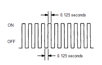
(h) Check that the MIL flashes as shown in the illustration.
(i) Start the engine.
(j) Check that the MIL turns off.
(k) Simulate the conditions of the malfunction described by the customer.
(l) Check for DTCs and Freeze Frame Data using the GTS.
 Dtc Check / Clear
DTC CHECK / CLEAR NOTICE: When the diagnosis system is changed from normal mode to check mode or vice versa, all DTCs and Freeze Frame Data recorded in normal mode are cleared...
 Freeze Frame Data
FREEZE FRAME DATA DESCRIPTION The ECM records vehicle and driving condition information as Freeze Frame Data the moment a DTC is stored. When troubleshooting, Freeze Frame Data can be helpful in determining whether the vehicle was moving or stationary, whether the engine was warmed up or not, whether the air fuel ratio was lean or rich, as well as other data recorded at the time of a malfunction...
Other information:
Toyota Yaris XP210 (2020-2026) Owner's Manual: Owner Maintenance Precautions
The owner or a qualified service technician should make these vehicle inspections at the indicated intervals to ensure safe and dependable operation. Bring any problem to the attention of your Toyota dealer or qualified service technician as soon as possible...
Toyota Yaris XP210 (2020-2026) Owner's Manual: Declaration of Conformity
K..
Categories
- Manuals Home
- Toyota Yaris Owners Manual
- Toyota Yaris Service Manual
- Fuel Gauge
- Brake System Control Module "A" System Voltage System Voltage Low (C137BA2)
- Power Integration No.1 System Missing Message (B235287,B235587,B235787-B235987)
- New on site
- Most important about car
Break-In Period
No special break-in is necessary, but a few precautions in the first 600 miles (1,000 km) may add to the performance, economy, and life of the vehicle.
Do not race the engine. Do not maintain one constant speed, either slow or fast, for a long period of time. Do not drive constantly at full-throttle or high engine rpm for extended periods of time. Avoid unnecessary hard stops. Avoid full-throttle starts.