Toyota Yaris: Clutch Unit / Installation
INSTALLATION
CAUTION / NOTICE / HINT
NOTICE:
When the manual transaxle assembly is removed, be sure to use a new clutch release cylinder with bearing assembly and new installation bolts. Removal of the manual transaxle assembly allows the compressed clutch release cylinder with bearing assembly to return to its original position. Dust from the moving section may damage the seal of the clutch release cylinder with bearing assembly, possibly causing clutch fluid leaks.
PROCEDURE
1. INSTALL COVER AND DISC CLUTCH SET
| (a) Insert SST into the clutch disc assembly, then insert them both into the flywheel sub-assembly. SST: 09301-00230 NOTICE:
|
|
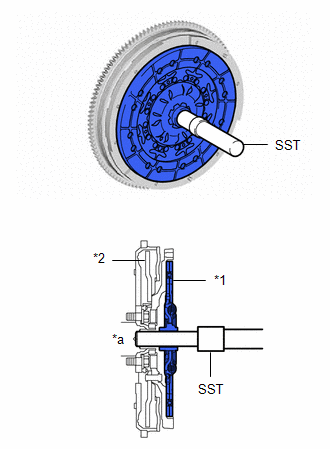
| (b) Align the matchmarks on the clutch cover assembly with the one on the flywheel sub-assembly. |
|
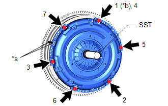
(c) Following the procedure shown in the illustration, tighten the 6 bolts in order, starting with the bolt located near the knock pin at the top.
SST: 09301-00230
Torque:
19.1 N·m {195 kgf·cm, 14 ft·lbf}
HINT:
- Following the order in the illustration, tighten the bolts evenly one at a time.
- Move SST up and down, right and left lightly after checking that the clutch disc assembly is in the center, and tighten the bolts.
2. INSPECT AND ADJUST CLUTCH COVER ASSEMBLY
| (a) Using a dial indicator with a roller instrument, check the diaphragm spring tip alignment. Maximum Non-alignment: 0.5 mm (0.0197 in.) |
|
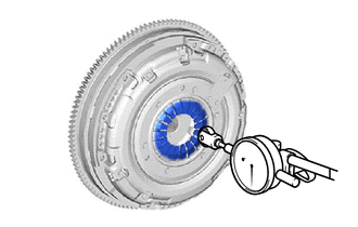
| (b) If the alignment is not as specified, using SST, adjust the diaphragm spring tip alignment. SST: 09333-00013 |
|

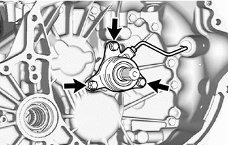
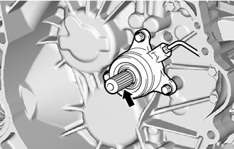
3. INSTALL CLUTCH RELEASE CYLINDER WITH BEARING ASSEMBLY
| (a) Temporarily tighten the clutch release cylinder to bleeder tube to a new clutch release cylinder with bearing assembly. NOTICE: Do not allow any foreign matter such as dirt or dust to enter the clutch release cylinder to bleeder tube from the connecting part. |
|
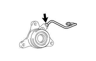
(b) Clean and degrease all installation surfaces for the clutch release cylinder with bearing assembly.
| (c) Install the clutch release cylinder with bearing assembly with 3 new bolts. Torque: 22.5 N·m {229 kgf·cm, 17 ft·lbf} NOTICE:
|
|
(d) Install the clutch tube boot to the manual transaxle assembly.
| (e) Temporarily tighten the clutch release cylinder to bleeder tube to the clutch release bleeder sub-assembly. |
|
| (f) Temporarily tighten the bolt and install the clutch release bleeder sub-assembly. NOTICE: Install the parts so that the rotation prevention tab of the clutch release bleeder sub-assembly is contacting the rib of the manual transaxle assembly. |
|
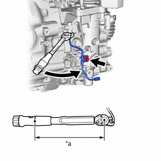
| (g) Using a 10 mm union nut wrench, fully tighten the clutch release cylinder to bleeder tube to the clutch release cylinder with bearing assembly. Torque: Specified Tightening Torque : 15.2 N·m {155 kgf·cm, 11 ft·lbf} NOTICE: Do not kink or damage the clutch release cylinder to bleeder tube. HINT:
|
|

(h) Apply clutch spline grease to the input shaft splines.
 | Clutch Spline Grease |
Grease:
Toyota Genuine Clutch Spline Grease or equivalent
4. INSTALL CLUTCH RELEASE BEARING PLATE
| (a) Install a new clutch release bearing plate to the clutch release cylinder with bearing assembly. NOTICE: After installing the clutch release bearing plate to the clutch release cylinder with bearing assembly, check that there are no gaps. |
|
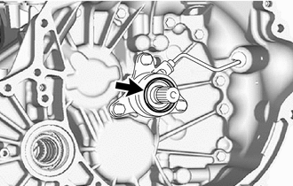
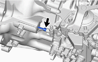
5. REMOVE CLUTCH RELEASE BLEEDER SUB-ASSEMBLY
(a) Disconnect the clutch release cylinder to bleeder tube from the clutch release bleeder sub-assembly.
(b) Remove the bolt and clutch release bleeder sub-assembly from the manual transaxle assembly.
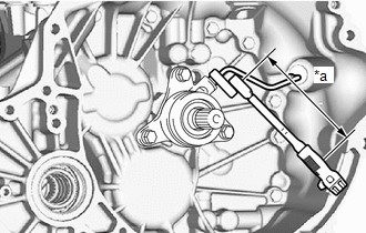
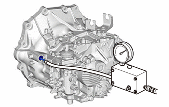
6. INSPECT CLUTCH PIPE LINE
| (a) Using SST, apply pressure of 100 kPa (1.0 kgf/cm2, 15 psi) to the clutch pipe location shown in the illustration and confirm that pressure is maintained for 15 seconds or more. SST: 09992-00242 If the pressure drops, replace the clutch release cylinder to bleeder tube. |
|
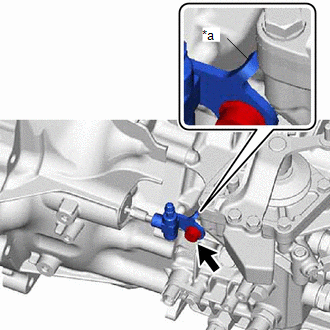
7. INSTALL CLUTCH RELEASE BLEEDER SUB-ASSEMBLY
| (a) Temporarily tighten the clutch release cylinder to bleeder tube to the clutch release bleeder sub-assembly. |
|

(b) Install the clutch release bleeder sub-assembly to the manual transaxle assembly with the bolt.
Torque:
20 N·m {204 kgf·cm, 15 ft·lbf}
NOTICE:
Install the parts so that the rotation prevention tab of the clutch release bleeder sub-assembly is contacting the rib of the manual transaxle assembly.
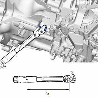
| (c) Using a 10 mm union nut wrench, fully tighten the clutch release cylinder to bleeder tube. Torque: Specified Tightening Torque : 15.2 N·m {155 kgf·cm, 11 ft·lbf} NOTICE:
HINT:
|
|

8. INSTALL BLEEDER CLUTCH RELEASE TUBE
(a) Install the clamp to the bleeder clutch release tube.
(b) Temporarily tighten the bleeder clutch release tube to the clutch release bleeder sub-assembly.
| (c) Install the bleeder clutch release tube to the manual transaxle assembly with the bolt. Torque: 10 N·m {102 kgf·cm, 7 ft·lbf} |
|
(d) Using a 10 mm union nut wrench, fully tighten the bleeder clutch release tube to the clutch release bleeder sub-assembly.
Torque:
Specified Tightening Torque :
15.2 N·m {155 kgf·cm, 11 ft·lbf}
NOTICE:
- Do not kink or damage the bleeder clutch release tube.
- Do not allow any foreign matter such as dirt or dust to enter the bleeder clutch release tube from the connecting part.
HINT:
-
Calculate the torque wrench reading when changing the fulcrum length of the torque wrench.
Click here

-
When using a union nut wrench (fulcrum length of 22 mm (0.866 in.)) + torque wrench (fulcrum length of 162 mm (6.38 in.)):
13.4 N*m (137 kgf*cm, 10 ft.*lbf)
9. INSTALL MANUAL TRANSAXLE ASSEMBLY
Click here

 Inspection
INSPECTION PROCEDURE 1. INSPECT CLUTCH DISC ASSEMBLY (a) Using a vernier caliper, measure the rivet head depth. Minimum Rivet Head Depth: 0.3 mm (0...

Other information:
Toyota Yaris XP210 (2020-2026) Reapir and Service Manual: Installation
INSTALLATION PROCEDURE 1. INSTALL AIR CONDITIONING AMPLIFIER ASSEMBLY (a) Connect the 3 connectors. (b) Engage the guide to install the air conditioning amplifier assembly. (c) Install the 3 screws. (d) Install the front floor carpet assembly with the 2 clips as shown in the illustration...
Toyota Yaris XP210 (2020-2026) Reapir and Service Manual: Removal
REMOVAL CAUTION / NOTICE / HINT CAUTION: Be sure to read Precaution thoroughly before servicing. Click here NOTICE: If a front seat airbag assembly has been deployed, replace the front seat airbag assembly, front seatback frame sub-assembly, separate type front seatback pad, separate type front seatback cover and front seatback pad with cover with the necessary parts in accordance with the extent of the collision damage...
Categories
- Manuals Home
- Toyota Yaris Owners Manual
- Toyota Yaris Service Manual
- To Set Speed
- Power Integration No.1 System Missing Message (B235287,B235587,B235787-B235987)
- G16e-gts (engine Mechanical)
- New on site
- Most important about car
Fuel-Filler Lid and Cap
WARNING
When removing the fuel-filler cap, loosen the cap slightly and wait for any hissing to stop, then remove it
Fuel spray is dangerous. Fuel can burn skin and eyes and cause illness if ingested. Fuel spray is released when there is pressure in the fuel tank and the fuel-filler cap is removed too quickly.