Toyota Yaris: Smart Key System (for Entry Function) / Entry Exterior Alarm does not Sound
DESCRIPTION
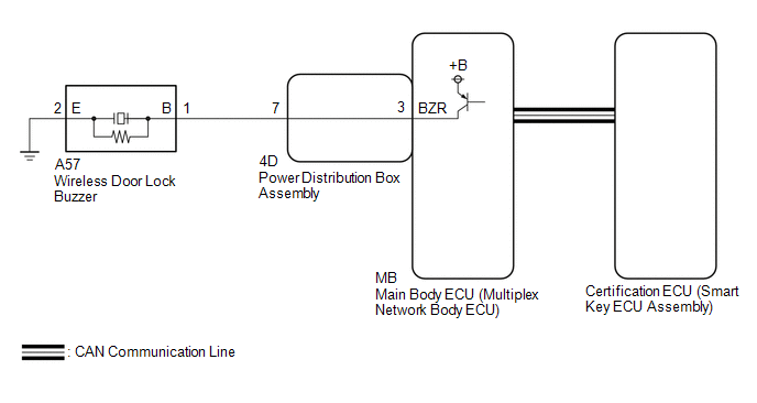
The smart key system (for Entry Function) uses the wireless door lock buzzer to perform various vehicle exterior warnings. When the conditions of each warning are met, the certification ECU (smart key ECU assembly) sends a buzzer activation request signal to the main body ECU (multiplex network body ECU) via CAN communication and the buzzer sounds.
WIRING DIAGRAM
CAUTION / NOTICE / HINT
NOTICE:
- When using the GTS with the ignition switch off, connect the GTS to the DLC3 and turn a courtesy light switch on and off at intervals of 1.5 seconds or less until communication between the GTS and the vehicle begins. Then select the vehicle type under manual mode and enter the following menus: Body Electrical / Smart Key. While using the GTS, periodically turn a courtesy light switch on and off at intervals of 1.5 seconds or less to maintain communication between the GTS and the vehicle.
-
The smart key system (for Entry Function) uses the CAN communication system. Inspect the communication function by following How to Proceed with Troubleshooting. Troubleshoot the smart key system (for Entry Function) after confirming that the communication systems are functioning properly.
Click here

-
Before replacing the certification ECU (smart key ECU assembly) or main body ECU (multiplex network body ECU), refer to Precaution.
Click here

- After repair, confirm that no DTCs are output.
PROCEDURE
| 1. | CHECK WIRELESS DOOR LOCK CONTROL SYSTEM |
(a) Check that the function operates normally.
Click here

| Result | Proceed to |
|---|---|
| Wireless door lock function operates normally | A |
| Wireless door lock function does not operate normally | B |
| B |
 | GO TO PROBLEM SYMPTOMS TABLE |
|

| 2. | READ VALUE USING GTS (EACH UNLOCK DETECTION SWITCH) |
(a) Read the Data List according to the display on the GTS.
Body Electrical > Main Body > Data List| Tester Display | Measurement Item | Range | Normal Condition | Diagnostic Note |
|---|---|---|---|---|
| FR Door Lock Position Switch Status | Front door RH unlock detection switch signal | Lock or Unlock | Lock: Front door RH locked Unlock: Front door RH unlocked | - |
| FL Door Lock Position Switch Status | Front door LH unlock detection switch signal | Lock or Unlock | Lock: Front door LH locked Unlock: Front door LH unlocked | - |
| Tester Display |
|---|
| FR Door Lock Position Switch Status |
| FL Door Lock Position Switch Status |
OK:
The GTS display changes correctly in response to the lock/unlock operation.
| NG |
 | GO TO LIGHTING SYSTEM (Proceed to Door Unlock Detection Switch Circuit) |
|

| 3. | PERFORM ACTIVE TEST USING GTS (WIRELESS BUZZER) |
(a) Perform Active Test according to the display on the GTS.
Body Electrical > Main Body > Active Test| Tester Display | Measurement Item | Control Range | Diagnostic Note |
|---|---|---|---|
| Wireless Buzzer | Wireless door lock buzzer | OFF/ON | - |
| Tester Display |
|---|
| Wireless Buzzer |
| Result | Proceed to |
|---|---|
| Wireless door lock buzzer does not sound | A |
| Wireless door lock buzzer sounds | B |
| B |
 | REPLACE CERTIFICATION ECU (SMART KEY ECU ASSEMBLY) |
|

| 4. | CHECK MAIN BODY ECU (MULTIPLEX NETWORK BODY ECU) |
(a) Disconnect the A57 wireless door lock buzzer connector.
(b) Perform the Active Test according to the display on the GTS.
Body Electrical > Main Body > Active Test| Tester Display | Measurement Item | Control Range | Diagnostic Note |
|---|---|---|---|
| Wireless Buzzer | Wireless door lock buzzer | OFF/ON | - |
| Tester Display |
|---|
| Wireless Buzzer |
(c) Measure the voltage according to the value(s) in the table below.
Standard Voltage:
| Tester Connection | Condition | Specified Condition |
|---|---|---|
| A57-1 (B) - A57-2 (E) | Active Test Wireless Buzzer is OFF | Below 1 V |
| Active Test Wireless Buzzer is ON | Pulse generation (frequency: 2 kHz, high voltage: 11 to 14 V, low voltage: below 1 V) |
| OK |
 | REPLACE WIRELESS DOOR LOCK BUZZER |
|

| 5. | CHECK HARNESS AND CONNECTOR (WIRELESS DOOR LOCK BUZZER - MAIN BODY ECU (MULTIPLEX NETWORK BODY ECU)) |
(a) Remove the main body ECU (multiplex network body ECU) from the power distribution box assembly.
Click here

(b) Reconnect the power distribution box assembly connectors.
(c) Measure the resistance according to the value(s) in the table below.
Standard Resistance:
| Tester Connection | Condition | Specified Condition |
|---|---|---|
| A57-1 (B) - MB-3 (BZR) | Always | Below 1 Ω |
| A57-2 (E) - Body ground | Always | Below 1 Ω |
| A57-1 (B) or MB-3 (BZR) - Other terminals and body ground | Always | 10 kΩ or higher |
| OK |
 | REPLACE MAIN BODY ECU (MULTIPLEX NETWORK BODY ECU) |
|

| 6. | CHECK HARNESS AND CONNECTOR (WIRELESS DOOR LOCK BUZZER - INSTRUMENT PANEL JUNCTION BLOCK ASSEMBLY) |
(a) Disconnect the 4D power distribution box assembly connector.
(b) Measure the resistance according to the value(s) in the table below.
Standard Resistance:
| Tester Connection | Condition | Specified Condition |
|---|---|---|
| A57-1 (B) - 4D-7 | Always | Below 1 Ω |
| A57-1 (B) or 4D-7 - Other terminals and body ground | Always | 10 kΩ or higher |
| OK |
 | REPLACE POWER DISTRIBUTION BOX ASSEMBLY |
| NG |
 | REPAIR OR REPLACE HARNESS OR CONNECTOR |
 Entry Interior Alarm does not Sound
DESCRIPTION The smart key system (for Entry Function) uses the buzzer in the combination meter assembly (meter ECU) to perform various vehicle interior warnings...
 Back Door Entry Unlock Function does not Operate
DESCRIPTION If the entry unlock function does not operate for the back door only, but the entry lock function operates, the request code is being transmitted properly from the back door...
Other information:
Toyota Yaris XP210 (2020-2026) Reapir and Service Manual: Installation
INSTALLATION CAUTION / NOTICE / HINT NOTICE: Work indoors with less dust and wind. Install the roof outside cover in an environment where the temperature is 20 to 30°C (68 to 86°F). Do not leave dirt such as old adhesive, bumps, dust and oil on the adhesive surface...
Toyota Yaris XP210 (2020-2026) Reapir and Service Manual: Reassembly
REASSEMBLY PROCEDURE 1. INSTALL ANTENNA CORD SUB-ASSEMBLY Click here 2. INSTALL INSTRUMENT PANEL PASSENGER WITHOUT DOOR AIRBAG ASSEMBLY Click here 3. INSTALL NO. 2 INSTRUMENT PANEL WIRE Click here 4. INSTALL INSTRUMENT CLUSTER FINISH PANEL ORNAMENT (a) Engage the guide and claws to install the instrument cluster finish panel ornament...
Categories
- Manuals Home
- Toyota Yaris Owners Manual
- Toyota Yaris Service Manual
- G16e-gts (engine Mechanical)
- Maintenance
- Brake System Control Module "A" System Voltage System Voltage Low (C137BA2)
- New on site
- Most important about car
Fuel Gauge
The fuel gauge shows approximately how much fuel is remaining in the tank when the ignition is switched ON. We recommend keeping the tank over 1/4 full.
