Toyota Yaris: Airbag System / Driver Frontal Stage 1 Deployment Control Circuit Resistance Below Threshold (B00011A)
DESCRIPTION
| DTC No. | Detection Item | DTC Detection Condition | Trouble Area | Warning Indicate | Test Mode / Check Mode |
|---|---|---|---|---|---|
| B00011A | Driver Frontal Stage 1 Deployment Control Circuit Resistance Below Threshold |
|
| Comes on | Applies to check mode |
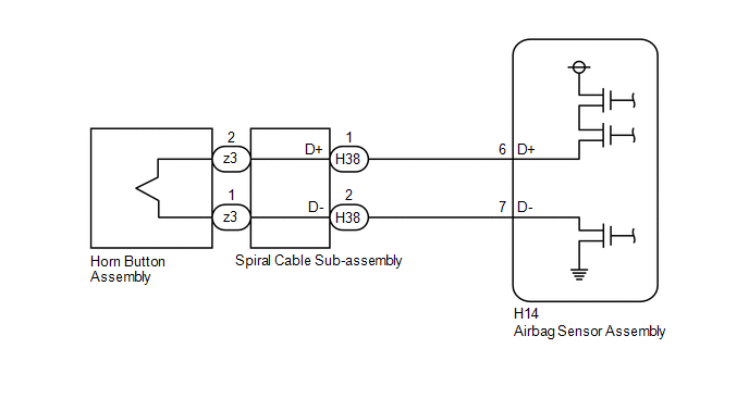
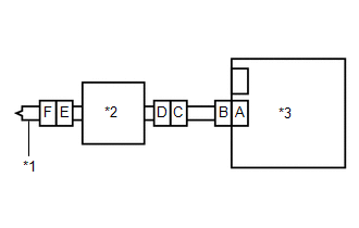
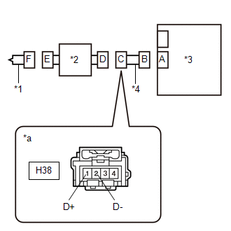
WIRING DIAGRAM
CAUTION / NOTICE / HINT
NOTICE:
After turning the ignition switch off, waiting time may be required before disconnecting the cable from the negative (-) auxiliary battery terminal.
Click here

HINT:
-
To perform the simulation method, select Check Mode with the GTS.
Click here

-
Perform the simulation method while checking the Data List.
Click here

-
When disconnecting and reconnecting the cable to the auxiliary battery terminal, there is an automatic learning function that completes learning when the respective system is used.
Click here

PROCEDURE
| 1. | CHECK CURRENT DTC |
(a) Turn the ignition switch to ON, and wait for at least 60 seconds.
(b) Check for DTCs.
Body Electrical > SRS Airbag > Trouble Codes| Result | Proceed to |
|---|---|
| Current B00011A is output | A |
| History B00011A is output | B |
| B |
 | USE SIMULATION METHOD TO CHECK |
|

| 2. | CHECK CONNECTION OF CONNECTORS |
(a) Turn the ignition switch off.
(b) Disconnect the cable from the negative (-) auxiliary battery terminal.
CAUTION:
Wait at least 60 seconds after disconnecting the cable from the negative (-) auxiliary battery terminal to disable the SRS system.
(c) Check that the connectors are properly connected to the horn button assembly, spiral cable sub-assembly and airbag sensor assembly.
OK:
The connectors are properly connected.
| NG |
 | CONNECT CONNECTORS PROPERLY |
|

| 3. | CHECK CONNECTORS |
| (a) Disconnect the connectors from the horn button assembly, spiral cable sub-assembly and airbag sensor assembly. |
|
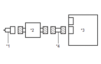
(b) Check that the terminals of the connectors are not deformed or damaged.
OK:
The terminals of the connectors are not deformed or damaged.
(c) Check that the short springs of the activation prevention mechanisms of the wire harness connector and spiral cable sub-assembly connector are not deformed or damaged.
OK:
The short springs are not deformed or damaged.
(d) Check that the spiral cable sub-assembly connector (on the horn button assembly side) is not loose, deformed or damaged.
OK:
The airbag connector locking button is not disengaged, and the claw of the lock is not deformed or damaged.
| NG |
 | REPLACE SPIRAL CABLE SUB-ASSEMBLY OR REPAIR OR REPLACE WIRE HARNESS |
|

| 4. | CHECK HORN BUTTON ASSEMBLY |
| (a) Connect the connectors to the airbag sensor assembly and spiral cable sub-assembly. |
|
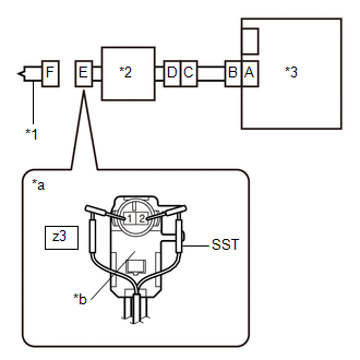
(b) Connect the white wire side of SST (resistance 2.1 Ω) to connector E (light green connector).
CAUTION:
Never connect a tester to the horn button assembly for measurement, as this may lead to a serious injury due to airbag deployment.
NOTICE:
- Do not forcibly insert SST into the terminals of the connector when connecting it.
- Insert SST straight into the terminals of the connector.
SST: 09843-18061
(c) Connect the cable to the negative (-) auxiliary battery terminal.
(d) Turn the ignition switch to ON, and wait for at least 60 seconds.
(e) Clear the DTCs stored in memory.
Body Electrical > SRS Airbag > Clear DTCs(f) Turn the ignition switch off.
|

| 5. | CHECK HORN BUTTON ASSEMBLY |
(a) Turn the ignition switch to ON, and wait for at least 60 seconds.
(b) Check for DTCs.
Body Electrical > SRS Airbag > Trouble CodesHINT:
Codes other than DTC B00011A may be output at this time, but they are not related to this check.
| Result | Proceed to |
|---|---|
| B00011A is not output | A |
| B00011A is output | B |
(c) Turn the ignition switch off.
(d) Disconnect the cable from the negative (-) auxiliary battery terminal.
CAUTION:
Wait at least 60 seconds after disconnecting the cable from the negative (-) auxiliary battery terminal to disable the SRS system.
(e) Disconnect SST from connector E.
| A |
 | REPLACE HORN BUTTON ASSEMBLY |
|

| 6. | CHECK DRIVER SEAT AIRBAG SQUIB CIRCUIT (SHORT) |
| (a) Disconnect the connector from the airbag sensor assembly. |
|
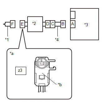
(b) Release the activation prevention mechanism built into connector B.
HINT:
Click here

(c) Measure the resistance according to the value(s) in the table below.
Standard Resistance:
| Tester Connection | Condition | Specified Condition |
|---|---|---|
| z3-2 - z3-1 | Always | 1 MΩ or higher |
(d) Restore the released activation prevention mechanism of connector B to the original condition.
| NG |
 | GO TO STEP 9 |
|

| 7. | CLEAR DTC |
| (a) Connect the connectors to the horn button assembly and airbag sensor assembly. |
|
(b) Connect the cable to the negative (-) auxiliary battery terminal.
(c) Turn the ignition switch to ON, and wait for at least 60 seconds.
(d) Clear the DTCs stored in memory.
Body Electrical > SRS Airbag > Clear DTCs(e) Turn the ignition switch off.
|

| 8. | CHECK DTC |
(a) Turn the ignition switch to ON, and wait for at least 60 seconds.
(b) Check for DTCs.
Body Electrical > SRS Airbag > Trouble CodesHINT:
Codes other than DTC B00011A may be output at this time, but they are not related to this check.
| Result | Proceed to |
|---|---|
| B00011A is not output | A |
| B00011A is output | B |
| A |
 | USE SIMULATION METHOD TO CHECK |
| B |
 | REPLACE AIRBAG SENSOR ASSEMBLY |
| 9. | CHECK WIRE HARNESS (SHORT) |
| (a) Disconnect the connector from the spiral cable sub-assembly. |
|
(b) Release the activation prevention mechanism built into connector B.
HINT:
Click here

(c) Measure the resistance according to the value(s) in the table below.
Standard Resistance:
| Tester Connection | Condition | Specified Condition |
|---|---|---|
| H38-1 (D+) - H38-2 (D-) | Always | 1 MΩ or higher |
(d) Restore the released activation prevention mechanism of connector B to the original condition.
| OK |
 | REPLACE SPIRAL CABLE SUB-ASSEMBLY |
| NG |
 | REPAIR OR REPLACE HARNESS OR CONNECTOR |
 Driver Frontal Stage 1 Deployment Control Circuit Open (B000113)
DESCRIPTION DTC No. Detection Item DTC Detection Condition Trouble Area Warning Indicate Test Mode / Check Mode B000113 Driver Frontal Stage 1 Deployment Control Circuit Open
The airbag sensor assembly detects an open in the driver seat airbag squib circuit for 2 seconds
Spiral cable sub-assembly malfunction
Horn button assembly malfunction
Airbag sensor assembly malfunction
Harness or connector
Spiral cable sub-assembly
Horn button assembly
Airbag sensor assembly
Comes on Applies to check mode WIRING DIAGRAM
CAUTION / NOTICE / HINT NOTICE: After turning the ignition switch off, waiting time may be required before disconnecting the cable from the negative (-) auxiliary battery terminal...
 SRS Warning Light Remains ON
DESCRIPTION The SRS warning light is located in the combination meter assembly. When the SRS is normal, the SRS warning light comes on for approximately 6 seconds after the ignition switch is turned from off to ON, and then turns off automatically...
Other information:
Toyota Yaris XP210 (2020-2025) Owner's Manual: Engine Coolant
Inspecting Coolant Level Inspect the antifreeze protection and coolant level in the coolant reservoir at least once a year—at the beginning of the winter season—and before traveling where temperatures may drop below freezing. Inspect the condition and connections of all cooling system and heater hoses...
Toyota Yaris XP210 (2020-2025) Reapir and Service Manual: Lost Communication with Steering Angle Sensor Module Missing Message (U012687,U010087,U012987,U014087,U023A87)
DESCRIPTION The power steering ECU assembly receives signals from the steering sensor, skid control ECU (brake actuator assembly), forward recognition camera, ECM and clearance warning ECU assembly via CAN communication. DTC No. Detection Item DTC Detection Condition Trouble Area Warning Indicate Return-to-normal Condition Note U010087 Lost Communication With ECM/PCM "A" Missing Message Lost communication with ECM CAN communication system ECM EPS warning light: Does not come on After normal confirmation - U012687 Lost Communication with Steering Angle Sensor Module Missing Message Lost communication with steering sensor CAN communication system Steering sensor EPS warning light: Does not come on After normal confirmation - U012987 Lost Communication with Brake System Control Module Missing Message Lost communication with skid control ECU (brake booster with master cylinder assembly) CAN communication system Skid control ECU (Brake booster with master cylinder assembly)(for TMC Made HV Model) Skid control ECU (Brake actuator assembly)(for TMMF Made HV Model) EPS warning light: Does not come on After normal confirmation - U014087 Lost Communication with Body Control Module Missing Message Lost communication with main body ECU (multiplex network body ECU) CAN communication system Main body ECU (multiplex network body ECU) EPS warning light: Does not come on After normal confirmation - U023A87 Lost Communication with Image Processing Module "A" Missing Message Lost communication with forward recognition camera CAN communication system Forward recognition camera EPS warning light: Does not come on After normal confirmation w/ Toyota Safety Sense PROCEDURE 1...
Categories
- Manuals Home
- Toyota Yaris Owners Manual
- Toyota Yaris Service Manual
- Removal
- Battery Monitor Module General Electrical Failure (P058A01)
- Engine Start Function When Key Battery is Dead
- New on site
- Most important about car
Break-In Period
No special break-in is necessary, but a few precautions in the first 600 miles (1,000 km) may add to the performance, economy, and life of the vehicle.
Do not race the engine. Do not maintain one constant speed, either slow or fast, for a long period of time. Do not drive constantly at full-throttle or high engine rpm for extended periods of time. Avoid unnecessary hard stops. Avoid full-throttle starts.