Toyota Yaris: Airbag System / SRS Warning Light Remains ON
DESCRIPTION
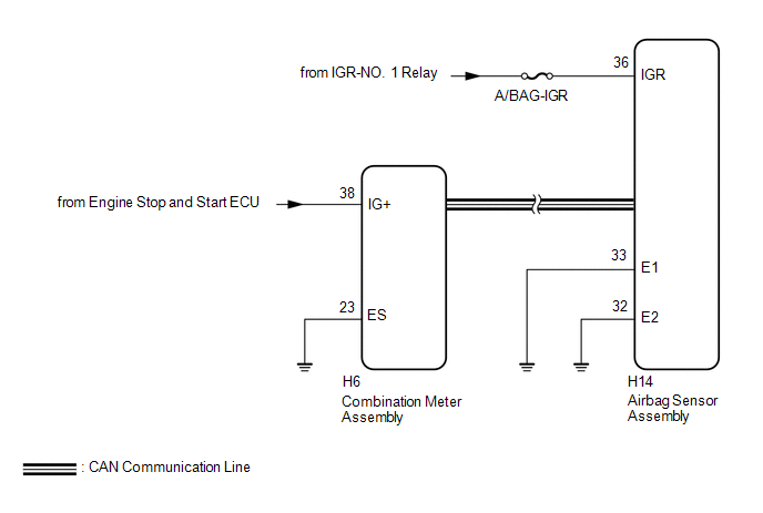
The SRS warning light is located in the combination meter assembly.
When the SRS is normal, the SRS warning light comes on for approximately 6 seconds after the ignition switch is turned from off to ON, and then turns off automatically.
If there is a malfunction in the SRS, the SRS warning light comes on to inform the driver of a problem.
If a malfunction occurs in the airbag sensor assembly, combination meter assembly or wire harness connected to the airbag sensor assembly or combination meter assembly, the SRS warning light comes on.
The SRS is equipped with a voltage-increase circuit (DC-DC converter) in the airbag sensor assembly in case the power source voltage drops.
When the auxiliary battery voltage drops, the voltage-increase circuit (DC-DC converter) functions to increase the voltage of the SRS to normal voltage. In addition, when the voltage drops, the SRS warning light will illuminate.
The SRS warning light automatically turns off when the power source voltage returns to normal.
The signal to illuminate the SRS warning light is transmitted from the airbag sensor assembly to the combination meter assembly via CAN communication.
WIRING DIAGRAM
CAUTION / NOTICE / HINT
NOTICE:
-
After turning the ignition switch off, waiting time may be required before disconnecting the cable from the negative (-) auxiliary battery terminal.
Click here

- Inspect the fuses for circuits related to this system before performing the following procedure.
- When replacing the combination meter assembly, always replace it with a new one. If a combination meter assembly which was installed to another vehicle is used, the information stored in it will not match the information from the vehicle and a DTC may be stored.
HINT:
When disconnecting and reconnecting the cable to the auxiliary battery terminal, there is an automatic learning function that completes learning when the respective system is used.
Click here

PROCEDURE
| 1. | CHECK VEHICLE CONTROL HISTORY (RoB) |
(a) Check for Vehicle Control History (RoB) codes.
Body Electrical > SRS Airbag > Utility| Tester Display |
|---|
| Vehicle Control History (RoB) |
| Result | Proceed to |
|---|---|
| Code X210B is output | A |
| Code X210B is not output | B |
| B |
 | GO TO STEP 4 |
|

| 2. | CHECK AUXILIARY BATTERY VOLTAGE |
(a) Measure the voltage of the auxiliary battery with the ignition switch off.
Standard Voltage:
11 to 14 V
| NG |
 | REPLACE OR RECHARGE AUXILIARY BATTERY |
|

| 3. | CHECK WIRE HARNESS (AIRBAG SENSOR ASSEMBLY - AUXILIARY BATTERY AND BODY GROUND) |
| (a) Connect the cable to the negative (-) auxiliary battery terminal. |
|

(b) Turn the ignition switch to ON.
(c) Operate all components of the electrical systems (defogger, wipers, headlights, heater blower, etc.).
(d) Measure the voltage according to the value(s) in the table below.
Standard Voltage:
| Tester Connection | Switch Condition | Specified Condition |
|---|---|---|
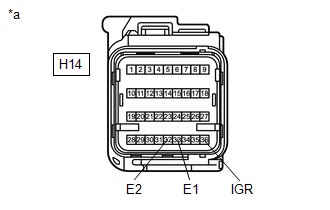
| H14-36 (IGR) - Body ground | Ignition switch ON | 8 to 16 V |
(e) Turn the ignition switch off.
(f) Measure the resistance according to the value(s) in the table below.
Standard Resistance:
| Tester Connection | Condition | Specified Condition |
|---|---|---|
| H14-33 (E1) - Body ground | Always | Below 1 Ω |
| H14-32 (E2) - Body ground | Always | Below 1 Ω |
| OK |
 | END (POWER SOURCE VOLTAGE DROPPED TEMPORARILY, BUT HAS RETURNED TO NORMAL) |
| NG |
 | REPAIR OR REPLACE HARNESS OR CONNECTOR |
| 4. | CHECK SRS WARNING LIGHT OPERATION |
(a) Turn the ignition switch to ON and check the SRS warning light condition.
HINT:
The primary check is performed for approximately 6 seconds after the ignition switch is turned to ON.
| Result | Proceed to |
|---|---|
| After the primary check period, the SRS warning light remains on. | A |
| After the primary check period, the SRS warning light turns off and comes on again. | B |
| B |
 | GO TO STEP 9 |
|

| 5. | CHECK AUXILIARY BATTERY VOLTAGE |
(a) Measure the voltage of the auxiliary battery with the ignition switch off.
Standard Voltage:
11 to 14 V
| NG |
 | REPLACE OR RECHARGE AUXILIARY BATTERY |
|

| 6. | CHECK CONNECTOR (AIRBAG SENSOR ASSEMBLY SIDE) |
(a) Turn the ignition switch off.
(b) Disconnect the cable from the negative (-) auxiliary battery terminal.
CAUTION:
Wait at least 60 seconds after disconnecting the cable from the negative (-) auxiliary battery terminal to disable the SRS system.
(c) Check that the connector is properly connected to the airbag sensor assembly.
OK:
The connector is properly connected.
HINT:
If the connector is not properly connected, reconnect the connector and proceed to the next inspection.
(d) Disconnect the connector from the airbag sensor assembly.
(e) Check that the terminals of the connector are not deformed or damaged.
OK:
The terminals are not deformed or damaged.
| NG |
 | REPAIR OR REPLACE HARNESS OR CONNECTOR |
|

| 7. | CHECK WIRE HARNESS (AIRBAG SENSOR ASSEMBLY - AUXILIARY BATTERY AND BODY GROUND) |
| (a) Connect the cable to the negative (-) auxiliary battery terminal. |
|
(b) Turn the ignition switch to ON.
(c) Operate all components of the electrical systems (defogger, wipers, headlights, heater blower, etc.).
(d) Measure the voltage according to the value(s) in the table below.
Standard Voltage:
| Tester Connection | Switch Condition | Specified Condition |
|---|---|---|
| H14-36 (IGR) - Body ground | Ignition switch ON | 8 to 16 V |
(e) Turn the ignition switch off.
(f) Measure the resistance according to the value(s) in the table below.
Standard Resistance:
| Tester Connection | Condition | Specified Condition |
|---|---|---|
| H14-33 (E1) - Body ground | Always | Below 1 Ω |
| H14-32 (E2) - Body ground | Always | Below 1 Ω |
| NG |
 | REPAIR OR REPLACE HARNESS OR CONNECTOR |
|

| 8. | CHECK SRS WARNING LIGHT |
| (a) Turn the ignition switch to ON and check the SRS warning light condition. OK: After the primary check period, the SRS warning light turns off for approximately 10 seconds and then turns back on. HINT: The primary check period is approximately 6 seconds after the ignition switch is turned to ON. |
|
| OK |
 | REPLACE AIRBAG SENSOR ASSEMBLY |
| NG |
 | REPLACE COMBINATION METER ASSEMBLY |
| 9. | CHECK CAN COMMUNICATION SYSTEM |
(a) Using the GTS, check if the CAN communication system is functioning normally.
OK:
CAN communication system is functioning normally.
HINT:
Refer to Communication Bus Check in CAN Communication System.
Click here

| NG |
 | GO TO CAN COMMUNICATION SYSTEM |
|

| 10. | CHECK AUXILIARY BATTERY VOLTAGE |
(a) Measure the voltage of the auxiliary battery with the ignition switch off.
Standard Voltage:
11 to 14 V
| NG |
 | REPLACE OR RECHARGE AUXILIARY BATTERY |
|

| 11. | CHECK CONNECTOR (AIRBAG SENSOR ASSEMBLY SIDE) |
(a) Turn the ignition switch off.
(b) Disconnect the cable from the negative (-) auxiliary battery terminal.
CAUTION:
Wait at least 60 seconds after disconnecting the cable from the negative (-) auxiliary battery terminal to disable the SRS system.
(c) Check that the connector is properly connected to the airbag sensor assembly.
OK:
The connector is properly connected.
HINT:
If the connector is not properly connected, reconnect the connector and proceed to the next inspection.
(d) Disconnect the connector from the airbag sensor assembly.
(e) Check that the terminals of the connector are not deformed or damaged.
OK:
The terminals are not deformed or damaged.
| NG |
 | REPAIR OR REPLACE HARNESS OR CONNECTOR |
|

| 12. | CHECK WIRE HARNESS (AIRBAG SENSOR ASSEMBLY - AUXILIARY BATTERY AND BODY GROUND) |
| (a) Connect the cable to the negative (-) auxiliary battery terminal. |
|

(b) Turn the ignition switch to ON.
(c) Operate all components of the electrical systems (defogger, wipers, headlights, heater blower, etc.).
(d) Measure the voltage according to the value(s) in the table below.
Standard Voltage:
| Tester Connection | Switch Condition | Specified Condition |
|---|---|---|
| H14-36 (IGR) - Body ground | Ignition switch ON | 8 to 16 V |
(e) Turn the ignition switch off.
(f) Measure the resistance according to the value(s) in the table below.
Standard Resistance:
| Tester Connection | Condition | Specified Condition |
|---|---|---|
| H14-33 (E1) - Body ground | Always | Below 1 Ω |
| H14-32 (E2) - Body ground | Always | Below 1 Ω |
| NG |
 | REPAIR OR REPLACE HARNESS OR CONNECTOR |
|

| 13. | CHECK CONNECTOR (COMBINATION METER ASSEMBLY SIDE) |
(a) Disconnect the cable from the negative (-) auxiliary battery terminal.
CAUTION:
Wait at least 60 seconds after disconnecting the cable from the negative (-) auxiliary battery terminal to disable the SRS system.
(b) Check that the connector is properly connected to the combination meter assembly.
OK:
The connector is properly connected.
HINT:
If the connector is not properly connected, reconnect the connector and proceed to the next inspection.
(c) Disconnect the connector from the combination meter assembly.
(d) Check that the terminals of the connector are not deformed or damaged.
OK:
The terminals are not deformed or damaged.
| NG |
 | REPAIR OR REPLACE HARNESS OR CONNECTOR |
|

| 14. | CHECK WIRE HARNESS (COMBINATION METER ASSEMBLY - AUXILIARY BATTERY AND BODY GROUND) |
| (a) Connect the cable to the negative (-) auxiliary battery terminal. |
|
(b) Turn the ignition switch to ON.
(c) Measure the voltage according to the value(s) in the table below.
Standard Voltage:
| Tester Connection | Switch Condition | Specified Condition |
|---|---|---|
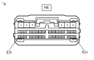
| H6-38 (IG+) - Body ground | Ignition switch ON | 10.5 to 16 V |
(d) Turn the ignition switch off.
(e) Measure the resistance according to the value(s) in the table below.
Standard Resistance:
| Tester Connection | Condition | Specified Condition |
|---|---|---|
| H6-23 (ES) - Body ground | Always | Below 1 Ω |
| NG |
 | REPAIR OR REPLACE HARNESS OR CONNECTOR |
|

| 15. | CHECK SRS WARNING LIGHT |
| (a) Disconnect the cable from the negative (-) auxiliary battery terminal. CAUTION: Wait at least 60 seconds after disconnecting the cable from the negative (-) auxiliary battery terminal to disable the SRS system. |
|

(b) Connect the connector to the combination meter assembly.
(c) Connect the cable to the negative (-) auxiliary battery terminal.
(d) Turn the ignition switch to ON and check the SRS warning light condition.
OK:
After the primary check period, the SRS warning light turns off for approximately 10 seconds and then turns back on.
HINT:
The primary check period is approximately 6 seconds after the ignition switch is turned to ON.
| OK |
 | REPLACE AIRBAG SENSOR ASSEMBLY |
| NG |
 | REPLACE COMBINATION METER ASSEMBLY |
 Driver Frontal Stage 1 Deployment Control Circuit Resistance Below Threshold (B00011A)
DESCRIPTION DTC No. Detection Item DTC Detection Condition Trouble Area Warning Indicate Test Mode / Check Mode B00011A Driver Frontal Stage 1 Deployment Control Circuit Resistance Below Threshold
The airbag sensor assembly detects a line short in the driver seat airbag squib circuit for 2 seconds during the primary check
Spiral cable sub-assembly malfunction
Horn button assembly malfunction
Airbag sensor assembly malfunction
Harness or connector
Spiral cable sub-assembly
Horn button assembly
Airbag sensor assembly
Comes on Applies to check mode WIRING DIAGRAM
CAUTION / NOTICE / HINT NOTICE: After turning the ignition switch off, waiting time may be required before disconnecting the cable from the negative (-) auxiliary battery terminal...
 SRS Warning Light does not Come ON
DESCRIPTION The SRS warning light is located in the combination meter assembly. When the SRS is normal, the SRS warning light comes on for approximately 6 seconds after the ignition switch is turned from off to ON, and then turns off automatically...
Other information:
Toyota Yaris XP210 (2020-2026) Reapir and Service Manual: Registration
REGISTRATION PROCEDURE 1. REPAIR INSTRUCTION CAUTION: As weak radio waves are emitted from the electrical key transmitter sub-assembly, if a pacemaker is being used, be sure to read the pacemaker instruction manual and the following. People with implantable cardiac pacemakers, cardiac resynchronization therapy-pacemakers or implantable cardioverter defibrillators should keep away from the Smart Key system antennas...
Toyota Yaris XP210 (2020-2026) Owner's Manual: Operating Tips for AAC
AAC stands for Advanced Audio Coding, which is standardized voice compression established by the ISO* 1 working group (MPEG). Audio data can be created and stored at a higher compression ratio than MP3. This unit plays files with the extensions (...
Categories
- Manuals Home
- Toyota Yaris Owners Manual
- Toyota Yaris Service Manual
- Power Integration No.1 System Missing Message (B235287,B235587,B235787-B235987)
- Removal
- Fuse Panel Description
- New on site
- Most important about car
Supplemental Restraint System (SRS) Precautions
The front and side supplemental restraint systems (SRS) include different types of air bags. Please verify the different types of air bags which are equipped on your vehicle by locating the “SRS AIRBAG” location indicators. These indicators are visible in the area where the air bags are installed.
The air bags are installed in the following locations:
The steering wheel hub (driver air bag) The front passenger dashboard (front passenger air bag) The outboard sides of the front seatbacks (side air bags) The front and rear window pillars, and the roof edge along both sides (curtain air bags)