Toyota Yaris: Steering Gear / Disassembly
DISASSEMBLY
PROCEDURE
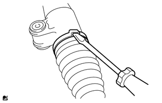
1. REMOVE STEERING RACK BOOT CLIP (for LH Side)
(a) Using pliers, remove the steering rack boot clip.
2. REMOVE STEERING RACK BOOT CLIP (for RH Side)
HINT:
Perform the same procedure as for the LH side.
3. REMOVE NO. 2 STEERING RACK BOOT CLAMP
| (a) Using a screwdriver, remove the No. 2 steering rack boot clamp. |
|
4. REMOVE NO. 1 STEERING RACK BOOT CLAMP
HINT:
Perform the same procedure as for the No. 2 steering rack boot clamp.
5. REMOVE NO. 2 STEERING RACK BOOT
(a) Remove the No. 2 steering rack boot.
NOTICE:
- Check that there is no water, foreign matter or rust inside of the removed No. 2 steering rack boot.
- If there is no water, foreign matter or rust inside of the No. 2 steering rack boot, pull out the rack bar and check for water, foreign matter or rust.
- If water or foreign matter in either part, replace them with a new steering gear assembly.
- In order to avoid water or foreign matter from adhering to the parts, do not touch the parts unless working in a dust-free, indoors environment.
6. REMOVE NO. 1 STEERING RACK BOOT
HINT:
Perform the same procedure as for the No. 2 steering rack boot.
 Removal
REMOVAL CAUTION / NOTICE / HINT The necessary procedures (adjustment, calibration, initialization, or registration) that must be performed after parts are removed, installed, or replaced during the steering gear assembly removal/installation are shown below...
 Inspection
INSPECTION PROCEDURE 1. INSPECT TIE ROD END SUB-ASSEMBLY LH (a) Secure the tie rod end sub-assembly LH in a vise between aluminum plates. NOTICE: Do not overtighten the vise...
Other information:
Toyota Yaris XP210 (2020-2026) Reapir and Service Manual: Freeze Frame Data
FREEZE FRAME DATA DESCRIPTION The ECM records vehicle and driving condition information as Freeze Frame Data the moment a DTC is stored. When troubleshooting, Freeze Frame Data can be helpful in determining whether the vehicle was moving or stationary, whether the engine was warmed up or not, whether the air fuel ratio was lean or rich, as well as other data recorded at the time of a malfunction...
Toyota Yaris XP210 (2020-2026) Reapir and Service Manual: Headlight LH Circuit (B243900,B243A00)
DESCRIPTION The light control LED ECU supplies internally boosted voltage to the light control LED ECU LH so that the current supplied to the LED is always maintained at a constant value. These DTCs are also output when the main body ECU (multiplex network body ECU) detects malfunctions while monitoring the applied voltage...
Categories
- Manuals Home
- Toyota Yaris Owners Manual
- Toyota Yaris Service Manual
- Key Battery Replacement
- G16e-gts (engine Mechanical)
- Brake System Control Module "A" System Voltage System Voltage Low (C137BA2)
- New on site
- Most important about car
Fuel Gauge
The fuel gauge shows approximately how much fuel is remaining in the tank when the ignition is switched ON. We recommend keeping the tank over 1/4 full.
