Toyota Yaris: Steering Gear / Removal
REMOVAL
CAUTION / NOTICE / HINT
The necessary procedures (adjustment, calibration, initialization, or registration) that must be performed after parts are removed, installed, or replaced during the steering gear assembly removal/installation are shown below.
Necessary Procedure After Parts Removed/Installed/Replaced| Replacement Part or Procedure | Necessary Procedure | Effect/Inoperative Function when Necessary Procedures are not Performed | Link |
|---|---|---|---|
| Front wheel alignment adjustment | ECU Data Initialization | Active torque split AWD system |
|
| Calibration |
|
|


PROCEDURE
1. REMOVE FRONT SUSPENSION CROSSMEMBER SUB-ASSEMBLY
Click here

2. REMOVE STEERING COLUMN HOLE COVER
(a) Remove the steering column hole cover from the steering link assembly.
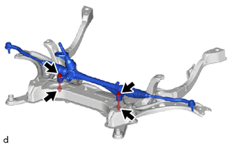
3. REMOVE STEERING LINK ASSEMBLY
| (a) Remove the 2 bolts, 2 washers, 2 nuts and steering link assembly from the front suspension crossmember sub-assembly. NOTICE: Loosen the nut with the bolt secured. |
|
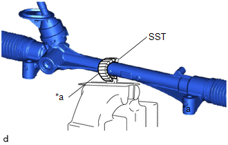
4. SECURE STEERING LINK ASSEMBLY
| (a) Using SST, secure the steering link assembly in a vise. SST: 09612-00012 HINT: Wrap SST with protective tape before use. |
|
5. REMOVE TIE ROD END SUB-ASSEMBLY LH
| (a) Put matchmarks on the tie rod end sub-assembly LH and steering gear assembly. |
|
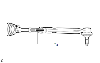
(b) Remove the tie rod end sub-assembly LH and lock nut.
6. REMOVE TIE ROD END SUB-ASSEMBLY RH
HINT:
Perform the same procedure as for the LH side.
 Components
COMPONENTS ILLUSTRATION
*1 STEERING COLUMN HOLE COVER *2 STEERING LINK ASSEMBLY
Tightening torque for "Major areas involving basic vehicle performance such as moving/turning/stopping": N*m (kgf*cm, ft...
 Disassembly
DISASSEMBLY PROCEDURE 1. REMOVE STEERING RACK BOOT CLIP (for LH Side) (a) Using pliers, remove the steering rack boot clip. 2. REMOVE STEERING RACK BOOT CLIP (for RH Side) HINT: Perform the same procedure as for the LH side...
Other information:
Toyota Yaris XP210 (2020-2026) Reapir and Service Manual: Ea67f Manual Transaxle Oil
ComponentsCOMPONENTS ILLUSTRATION *1 NO. 1 ENGINE UNDER COVER ASSEMBLY *2 ENGINE UNDER COVER LH *3 MANUAL TRANSMISSION FILLER PLUG *4 MANUAL TRANSMISSION DRAIN PLUG *5 GASKET - - N*m (kgf*cm, ft.*lbf): Specified torque ● Non-reusable part ReplacementREPLACEMENT PROCEDURE 1...
Toyota Yaris XP210 (2020-2026) Reapir and Service Manual: Fail-safe Chart
FAIL-SAFE CHART If any of the following DTCs are stored, the ECM enters fail-safe mode to allow the vehicle to be driven temporarily or stops fuel injection. DTC Code Component Fail-Safe Operation Fail-Safe Deactivation Condition P001100 P001200 VVT system Intake VVT maximum retarded contact...
Categories
- Manuals Home
- Toyota Yaris Owners Manual
- Toyota Yaris Service Manual
- Power Integration No.1 System Missing Message (B235287,B235587,B235787-B235987)
- Diagnostic Trouble Code Chart
- Key Battery Replacement
- New on site
- Most important about car
Fuel-Filler Lid and Cap
WARNING
When removing the fuel-filler cap, loosen the cap slightly and wait for any hissing to stop, then remove it
Fuel spray is dangerous. Fuel can burn skin and eyes and cause illness if ingested. Fuel spray is released when there is pressure in the fuel tank and the fuel-filler cap is removed too quickly.