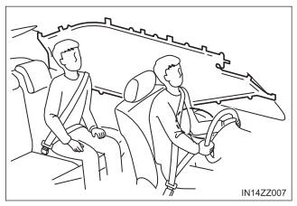
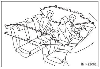
Toyota Yaris: How the SRS Air Bags Work / Curtain Air Bags
The curtain air bags are mounted in the front and rear window pillars, and the roof edge along both sides.
When the air bag crash sensors detect a side impact of greater than moderate force, the curtain air bag inflates quickly and helps to reduce injury mainly to the rear outboard passenger’s head caused by directly hitting interior parts such as a door or window.
For more details about air bag deployment, refer to “SRS Air Bag Deployment Criteria”.
In a side impact
Greater than moderate impact to one side of the vehicle will cause the curtain air bag on that side only to inflate.
Only one side curtain air bag will deploy on the side of the vehicle that receives the force of an impact.
In a roll-over
In response to a vehicle roll-over, both curtain air bags inflate.
Both curtain air bags will deploy after the roll-over accident is detected.
 Side Air Bags
The side air bags are mounted in the outboard sides of the front
seatbacks.
When the air bag crash sensors
detect a side impact of greater
than moderate force, the system inflates the side air bag
only on the side in which the
vehicle was hit...

Other information:
Toyota Yaris XP210 (2020-2026) Reapir and Service Manual: Customize Parameters
CUSTOMIZE PARAMETERS CUSTOMIZE SMART KEY SYSTEM (for Entry Function) HINT: The following items can be customized. NOTICE: When the customer requests a change in a function, first make sure that the function can be customized. Record the current settings before customizing...
Toyota Yaris XP210 (2020-2026) Reapir and Service Manual: Immobiliser Amp Missing Message (B278E87)
DESCRIPTION A transponder key amplifier is built into the certification ECU (smart key ECU assembly). When a communication malfunction occurs with the transponder key amplifier inside the certification ECU (smart key ECU assembly), this DTC is stored...
Categories
- Manuals Home
- Toyota Yaris Owners Manual
- Toyota Yaris Service Manual
- Brake System Control Module "A" System Voltage System Voltage Low (C137BA2)
- Maintenance
- Engine Start Function When Key Battery is Dead
- New on site
- Most important about car
Keys

To use the auxiliary key, press the knob and pull out the auxiliary key from the smart key.
