Toyota Yaris: Front Seat Side Airbag Assembly / Components
COMPONENTS
ILLUSTRATION
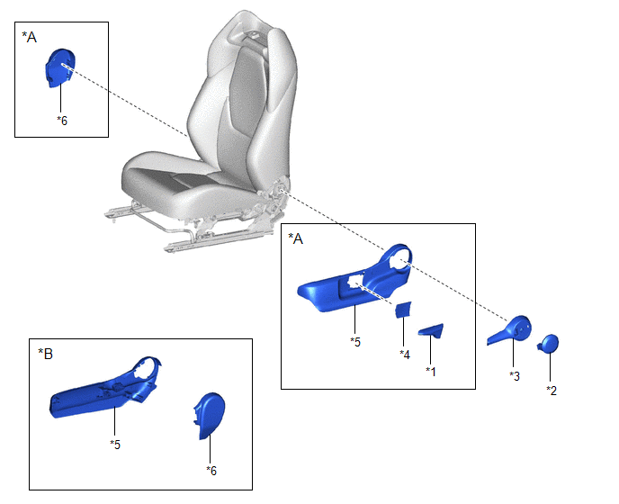
| *A | for Driver Side | *B | for Front Passenger Side |
| *1 | FRONT SEAT VERTICAL ADJUSTER HANDLE | *2 | NO.1 RECLINING HINGE COVER |
| *3 | RECLINING ADJUSTER RELEASE HANDLE | *4 | SEAT ADJUSTER COVER CAP |
| *5 | FRONT SEAT CUSHION SHIELD | *6 | FRONT SEAT INNER CUSHION SHIELD |
ILLUSTRATION
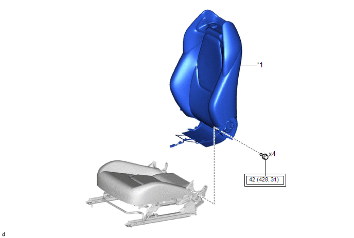
| *1 | SEPARATE TYPE FRONT SEATBACK ASSEMBLY | - | - |
 | Tightening torque for "Major areas involving basic vehicle performance such as moving/turning/stopping" : N*m (kgf*cm, ft.*lbf) | - | - |
ILLUSTRATION
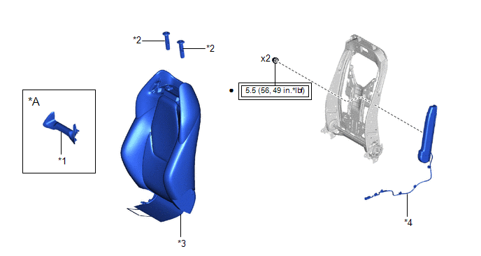
| *A | for Sports Seat Type | - | - |
| *1 | FRONT SEATBACK BEZEL | *2 | FRONT SEAT HEADREST SUPPORT ASSEMBLY |
| *3 | SEPARATE TYPE FRONT SEATBACK COVER WITH PAD | *4 | FRONT SEAT AIRBAG ASSEMBLY |
 | Tightening torque for "Major areas involving basic vehicle performance such as moving/turning/stopping" : N*m (kgf*cm, ft.*lbf) | ● | Non-reusable part |

 Removal
REMOVAL CAUTION / NOTICE / HINT The necessary procedures (adjustment, calibration, initialization, or registration) that must be performed after parts are removed, installed, or replaced during the front seat airbag assembly removal/installation are shown below...
Other information:
Toyota Yaris XP210 (2020-2026) Reapir and Service Manual: How To Proceed With Troubleshooting
CAUTION / NOTICE / HINT HINT: Use the following procedure to troubleshoot the power window control system. *: Use the GTS. PROCEDURE 1. VEHICLE BROUGHT TO WORKSHOP NEXT 2. CUSTOMER PROBLEM ANALYSIS HINT: In troubleshooting, confirm that the problem symptoms have been accurately identified...
Toyota Yaris XP210 (2020-2026) Reapir and Service Manual: Problem Symptoms Table
PROBLEM SYMPTOMS TABLE NOTICE: When replacing the combination meter assembly, always replace it with a new one. If a combination meter assembly which was installed to another vehicle is used, the information stored in it will not match the information from the vehicle and a DTC may be stored...
Categories
- Manuals Home
- Toyota Yaris Owners Manual
- Toyota Yaris Service Manual
- Headlights
- Adjustment
- Auto Lock/Unlock Function
- New on site
- Most important about car
Turning the Engine Off
Stop the vehicle completely. Manual transaxle: Shift into neutral and set the parking brake.Automatic transaxle: Shift the selector lever to the P position and set the parking brake.
Press the push button start to turn off the engine. The ignition position is off.