Toyota Yaris: Fog Light Assembly / Components
COMPONENTS
ILLUSTRATION
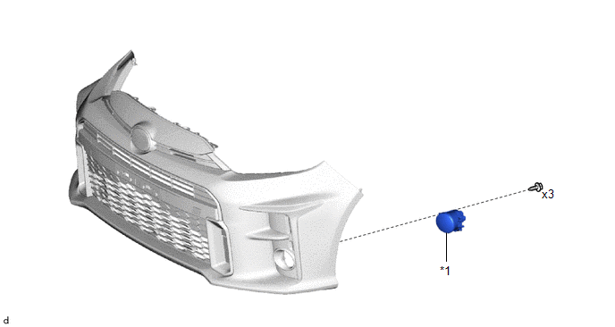
| *1 | FOG LIGHT ASSEMBLY | - | - |

 Removal
REMOVAL CAUTION / NOTICE / HINT HINT:
Use the same procedure for the RH side and LH side.
The following procedure is for the LH side.
PROCEDURE 1...
Other information:
Toyota Yaris XP210 (2020-2026) Reapir and Service Manual: Brake Warning Light Remains ON
DESCRIPTION This procedure is for troubleshooting when the brake system warning light remains on but no DTCs are output. The skid control ECU (brake actuator assembly) controls the brake system warning light in the combination meter assembly via CAN communication...
Toyota Yaris XP210 (2020-2026) Owner's Manual: Receiving an Incoming Call
When an incoming call is received, the incoming call notification screen is displayed. The “Incoming Call Notifications” setting must be on. Refer to Communication Settings. To accept the call, press the pick-up button on the audio control switch or select on the screen...
Categories
- Manuals Home
- Toyota Yaris Owners Manual
- Toyota Yaris Service Manual
- To Set Speed
- Fuel Gauge
- Immobilizer System
- New on site
- Most important about car
Supplemental Restraint System (SRS) Precautions
The front and side supplemental restraint systems (SRS) include different types of air bags. Please verify the different types of air bags which are equipped on your vehicle by locating the “SRS AIRBAG” location indicators. These indicators are visible in the area where the air bags are installed.
The air bags are installed in the following locations:
The steering wheel hub (driver air bag) The front passenger dashboard (front passenger air bag) The outboard sides of the front seatbacks (side air bags) The front and rear window pillars, and the roof edge along both sides (curtain air bags)
Copyright © 2026 www.toyaris4.com