Toyota Yaris: Engine Stop And Start Ecu / Components
COMPONENTS
ILLUSTRATION
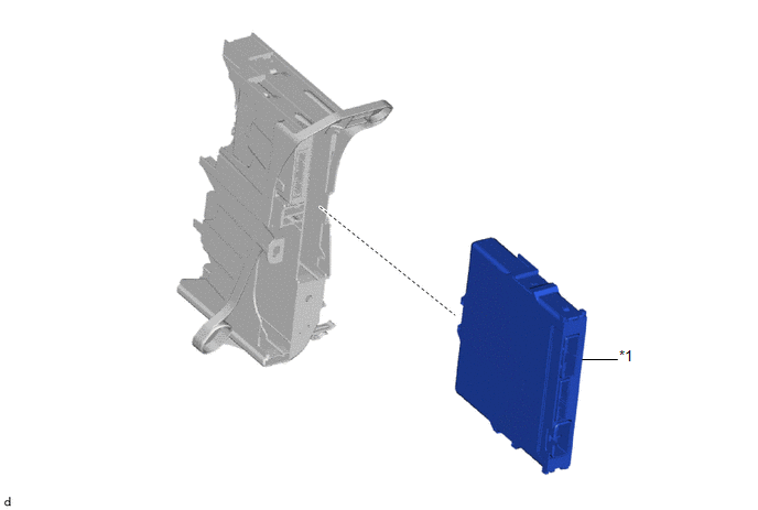
| *1 | ENGINE STOP AND START ECU | - | - |

 Removal
REMOVAL CAUTION / NOTICE / HINT The necessary procedures (adjustment, calibration, initialization or registration) that must be performed after parts are removed, installed, or replaced during the engine stop and start ECU removal/installation are shown below...
Other information:
Toyota Yaris XP210 (2020-2026) Reapir and Service Manual: Disassembly
DISASSEMBLY CAUTION / NOTICE / HINT NOTICE: Do not drop the power steering ECU assembly, strike it with tools or subject it to impacts. If the power steering ECU assembly is subjected to an impact, replace it with a new one. Do not pull the wire harness...
Toyota Yaris XP210 (2020-2026) Reapir and Service Manual: Removal
REMOVAL CAUTION / NOTICE / HINT The necessary procedures (adjustment, calibration, initialization, or registration) that must be performed after parts are removed and installed, or replaced during the main body ECU (multiplex network body ECU) removal/installation are shown below...
Categories
- Manuals Home
- Toyota Yaris Owners Manual
- Toyota Yaris Service Manual
- Maintenance
- Fuel Gauge
- Engine Start Function When Key Battery is Dead
- New on site
- Most important about car
Supplemental Restraint System (SRS) Precautions
The front and side supplemental restraint systems (SRS) include different types of air bags. Please verify the different types of air bags which are equipped on your vehicle by locating the “SRS AIRBAG” location indicators. These indicators are visible in the area where the air bags are installed.
The air bags are installed in the following locations:
The steering wheel hub (driver air bag) The front passenger dashboard (front passenger air bag) The outboard sides of the front seatbacks (side air bags) The front and rear window pillars, and the roof edge along both sides (curtain air bags)
Copyright © 2026 www.toyaris4.com