Toyota Yaris: Starter / Components
COMPONENTS
ILLUSTRATION
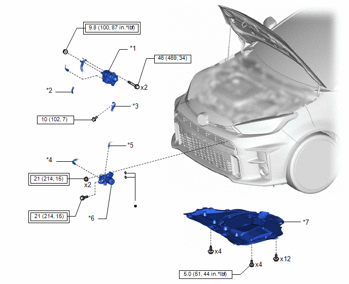
| *1 | STARTER ASSEMBLY | *2 | FLYWHEEL HOUSING SIDE COVER |
| *3 | WIRE HARNESS CLAMP BRACKET | *4 | NO. 5 WATER BY-PASS HOSE |
| *5 | NO. 1 ENGINE UNDER COVER ASSEMBLY | *6 | OIL COOLER ASSEMBLY |
| *7 | NO. 1 ENGINE UNDER COVER ASSEMBLY | - | - |
 | Tightening torque for "Major areas involving basic vehicle performance such as moving/turning/stopping": N*m (kgf*cm, ft.*lbf) |
 | N*m (kgf*cm, ft.*lbf): Specified torque |
| ● | Non-reusable part | - | - |
ILLUSTRATION
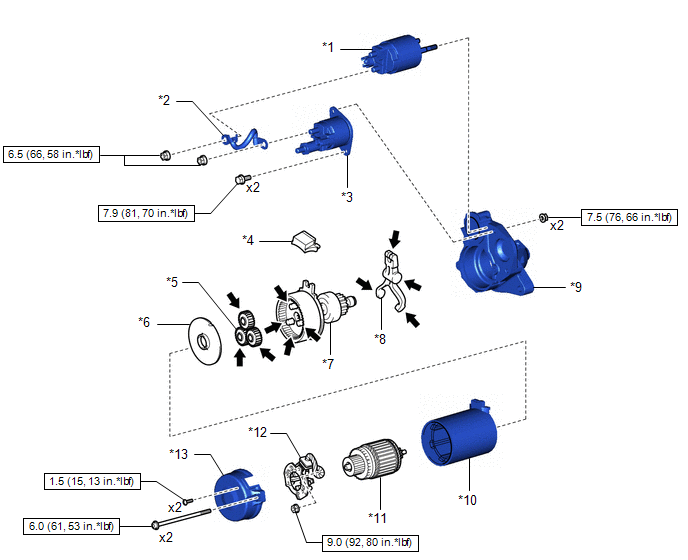
| *1 | MAGNET SWITCH | *2 | WIRE HARNESS |
| *3 | STARTER INRUSH CURRENT REDUCTION RELAY | *4 | RUBBER SEAL |
| *5 | PLANETARY GEAR | *6 | STARTER ARMATURE PLATE |
| *7 | STARTER CENTER BEARING CLUTCH SUB-ASSEMBLY | *8 | PINION DRIVE LEVER |
| *9 | STARTER DRIVE HOUSING ASSEMBLY | *10 | STARTER YOKE ASSEMBLY |
| *11 | STARTER ARMATURE ASSEMBLY | *12 | STARTER BRUSH HOLDER ASSEMBLY |
| *13 | STARTER COMMUTATOR END FRAMEASSEMBLY | - | - |
 | N*m (kgf*cm, ft.*lbf): Specified torque |
 | High-temperature grease |
 Starter
..
 Removal
REMOVAL CAUTION / NOTICE / HINT HINT: When the cable is disconnected / reconnected to the auxiliary battery terminal, systems temporarily stop operating...
Other information:
Toyota Yaris XP210 (2020-2026) Owner's Manual: Reporting Safety Defects (U.S.A.)
If you believe that your vehicle has a defect which could cause a crash or could cause injury or death, you should immediately inform the National Highway Traffic Safety Administration (NHTSA) in addition to notifying Toyota Motor Sales, U.S.A., Inc...
Toyota Yaris XP210 (2020-2026) Reapir and Service Manual: Jam Protection Function does not Operate
DESCRIPTION This symptom may occur for any of the power windows. The jam protection function operates within a specified range during the manual up or auto up operation. CAUTION / NOTICE / HINT NOTICE: If a power window regulator motor assembly has been replaced with a new one, initialize the power window control system...
Categories
- Manuals Home
- Toyota Yaris Owners Manual
- Toyota Yaris Service Manual
- Headlights
- Maintenance
- Immobilizer System
- New on site
- Most important about car
Fuel-Filler Lid and Cap
WARNING
When removing the fuel-filler cap, loosen the cap slightly and wait for any hissing to stop, then remove it
Fuel spray is dangerous. Fuel can burn skin and eyes and cause illness if ingested. Fuel spray is released when there is pressure in the fuel tank and the fuel-filler cap is removed too quickly.