Toyota Yaris: Fuel Pump / Components
COMPONENTS
ILLUSTRATION
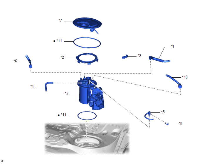
| *1 | CHARCOAL CANISTER OUTLET HOSE | *2 | FUEL PUMP GAUGE RETAINER |
| *3 | FUEL SUCTION WITH PUMP AND GAUGE TUBE ASSEMBLY | *4 | FUEL TANK EVAP TUBE SUB-ASSEMBLY |
| *5 | FUEL TANK MAIN TUBE SUB-ASSEMBLY | *6 | NO. 1 FUEL EVAPORATION TUBE SUB-ASSEMBLY |
| *7 | REAR FLOOR SERVICE HOLE COVER | *8 | NO. 1 FUEL TUBE CLAMP |
| *9 | TUBE JOINT CLIP | *10 | FUEL RETURN VENT TUBE SUB-ASSEMBLY |
| *11 | GASKET | - | - |
| ● | Non-reusable part | - | - |
ILLUSTRATION
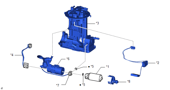
| *1 | FUEL PUMP | *2 | FUEL SENDER GAUGE ASSEMBLY |
| *3 | FUEL SUCTION WITH PUMP AND GAUGE TUBE ASSEMBLY | *4 | WIRE HARNESS |
| *5 | O-RING | *6 | SUB-ASSEMBLY SUPPORT |
| *7 | FUEL SUCTION TUBE | *8 | NO. 1 CAP |
| ● | Non-reusable part | - | - |
 Fuel Pump
..
 Removal
REMOVAL CAUTION / NOTICE / HINT The necessary procedures (adjustment, calibration, initialization or registration) that must be performed after parts are removed and installed, or replaced during fuel pump removal/installation are shown below...
Other information:
Toyota Yaris XP210 (2020-2026) Reapir and Service Manual: Installation
I..
Toyota Yaris XP210 (2020-2026) Reapir and Service Manual: Engine Coolant Temperature Sensor 1 Signal Stuck in Range (P01152A)
DESCRIPTION Refer to DTC P011511. Click here DTC No. Detection Item DTC Detection Condition Trouble Area MIL Note P01152A Engine Coolant Temperature Sensor 1 Signal Stuck in Range Either of the following conditions is met (2 trip detection logic): When engine is started cold and warmed up, the engine coolant temperature sensor value does not change...
Categories
- Manuals Home
- Toyota Yaris Owners Manual
- Toyota Yaris Service Manual
- How to connect USB port/Auxiliary jack
- Headlights
- Battery Monitor Module General Electrical Failure (P058A01)
- New on site
- Most important about car
Front Seat Belt Pretensioners
The front seat belt pretensioners are designed to deploy in moderate or severe frontal, near frontal collisions.
In addition, the pretensioners operate when a side collision or a rollover accident is detected. The pretensioners operate differently depending on what types of air bags are equipped. For more details about the seat belt pretensioner operation, refer to the SRS Air Bag Deployment Criteria.