Toyota Yaris: Front Camera / Before Starting Driving Adjustment
BEFORE STARTING DRIVING ADJUSTMENT
CAUTION / NOTICE / HINT
NOTICE:
When replacing the windshield glass of a vehicle equipped with a forward recognition camera, make sure to use a Toyota genuine part. If a non-Toyota genuine part is used, the forward recognition camera may not be able to be installed due to a missing bracket. Also, the dynamic radar cruise control system, lane control system, pre-collision system, front camera system or automatic high beam system may not operate properly due to a difference in the transmissivity or black ceramic border.
HINT:
-
Purpose of forward recognition camera optical axis learning:
- If the installation position or orientation of the forward recognition camera is changed due to it being replaced with a new one or the windshield glass sub-assembly being replaced or removed and installed, it is necessary to perform forward recognition camera optical axis learning for the forward recognition camera to learn the driving direction of the vehicle and its horizontal axis in order for each driving support system to operate correctly.
-
Driving direction of vehicle and horizontal axis
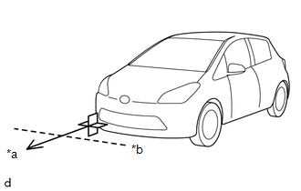
*a
Driving Direction
*b
Horizontal Axis
-
Before adjustment
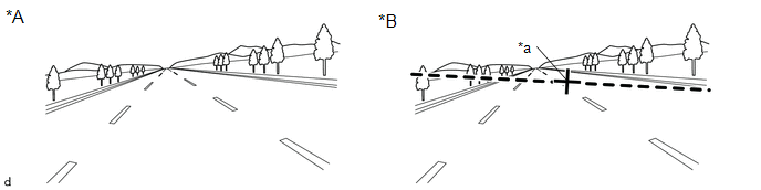
*A
When using a new forward recognition camera
*B
When reusing forward recognition camera
*a
Previously learned driving direction
-
-
-
After adjustment
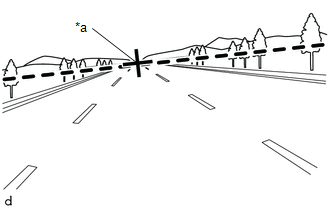
*a
Newly learned driving direction
-
Before adjustment
PROCEDURE
1. PERFORM DRIVING ADJUSTMENT
NOTICE:
- When performing the driving adjustment, obey all applicable traffic laws.
- Select a road where the driving adjustment can be carried out safely.
| (a) Driving adjustment concept
|
|
(b) Driving conditions
- Perform the adjustment outside during daytime, on a sunny or cloudy day.
- If preceding vehicles are present, they should be kept at a distance of at least 20 m (66 ft.)
- Perform the adjustment mainly on a straight road without incline or decline, with a dry and smooth road surface.
- Steer the vehicle straight without drifting or wobbling, and avoid sudden acceleration or deceleration.
- Drive at a vehicle speed of 40 km/h or more.
After driving the vehicle with all conditions met for approximately 5 to 15 minutes cumulatively, the adjustment will be completed.
HINT:
- If the adjustment does not complete even after driving for 15 minutes or more, change to a different driving route.
- If the adjustment does not complete even after driving for 30 minutes or more, perform adjustment by target recognition.
(c) Road environment
HINT:
When driving on a bumpy or unpaved road, making frequent accelerations and decelerations, etc., the camera condition may be unstable, which may cause adjustment to take a long time.
-
Road environments conducive to adjustment
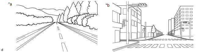
*a
Roads with continuous white lines
*b
Roads with objects such as buildings or utility poles
-
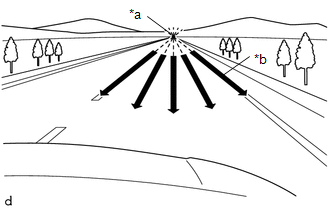
Road environments which hinder adjustment
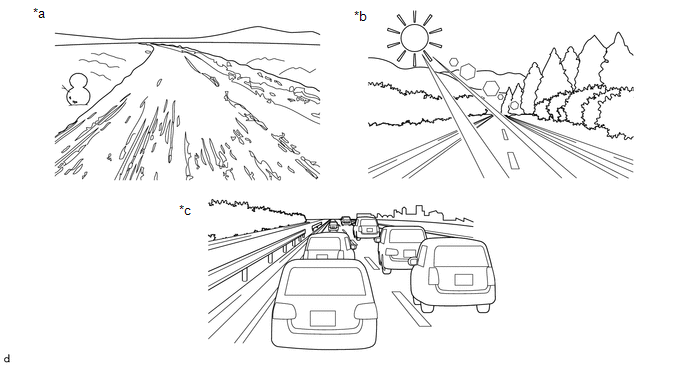
*a
Roads with scenery that does not change
*b
Backlit or high-glare environments
*c
When surrounded by moving vehicles
-
-
 Target Adjustment(one Time Recognition)
TARGET ADJUSTMENT(ONE TIME RECOGNITION) CAUTION / NOTICE / HINT NOTICE: Make sure to read Before Starting Adjustment before proceeding with work. Click here
PROCEDURE 1...
 Driving Adjustment
DRIVING ADJUSTMENT CAUTION / NOTICE / HINT NOTICE:
Make sure to read Before Starting Driving Adjustment before proceeding with work.
Click here
Make sure to perform the transition to online axis alignment mode with the vehicle stopped...
Other information:
Toyota Yaris XP210 (2020-2026) Reapir and Service Manual: Transmission Fluid Temperature Sensor "A" Circuit Short To Ground (P071011)
DESCRIPTION The manual transaxle oil temperature sensor (temperature sensor) installed inside the manual transaxle assembly detects the temperature of the fluid in the transaxle and outputs signals to the ECM according to the fluid temperature. DTC No...
Toyota Yaris XP210 (2020-2026) Reapir and Service Manual: How To Proceed With Troubleshooting
CAUTION / NOTICE / HINT HINT: Use the following procedure listed to troubleshoot the Active Torque Split AWD System. *: Use the GTS. PROCEDURE 1. VEHICLE BROUGHT TO WORKSHOP NEXT 2. INSPECT AUXILIARY BATTERY VOLTAGE Standard voltage: 11 to 14 V If the voltage is below 11 V, recharge or replace the auxiliary battery before proceeding to the next step...
Categories
- Manuals Home
- Toyota Yaris Owners Manual
- Toyota Yaris Service Manual
- G16e-gts (engine Mechanical)
- Fuel Gauge
- How to use USB mode
- New on site
- Most important about car
Front Seat Belt Pretensioners
The front seat belt pretensioners are designed to deploy in moderate or severe frontal, near frontal collisions.
In addition, the pretensioners operate when a side collision or a rollover accident is detected. The pretensioners operate differently depending on what types of air bags are equipped. For more details about the seat belt pretensioner operation, refer to the SRS Air Bag Deployment Criteria.