Toyota Yaris: Transmission Control Cable / Adjustment
ADJUSTMENT
PROCEDURE
1. SECURE VEHICLE
(a) Fully apply the parking brake and chock a wheel.
CAUTION:
-
Make sure to apply the parking brake and chock a wheel before performing this procedure.
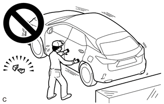
- If the vehicle is not secure and the shift lever is moved to neutral, the vehicle may suddenly move, possibly resulting in an accident or serious injury.
2. REMOVE REAR CONSOLE BOX ASSEMBLY
Click here

3. REMOVE AIR CLEANER ASSEMBLY
Click here

4. ADJUST TRANSMISSION CONTROL CABLE ASSEMBLY
HINT:
- After the floor shift shift lever assembly or the transmission control cable assembly is replaced, be sure to adjust the transmission control cable assembly.
- If the shift lever does not move (or the shift lever is difficult to move) to the 1st or 2nd position, or if it is possible to move the shift lever to the reverse position without pulling up the slider shaft, the length of the transmission control cable assembly must be adjusted.
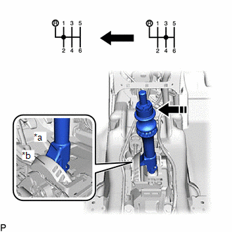
| (a) Remove the clip and disconnect the transmission control select cable from the floor shift shift lever assembly. |
|
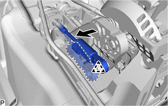
| (b) Slide the slider of the transmission control select cable in the direction indicated by the arrow in the illustration and pull the lock piece outward. |
|
| (c) Connect the transmission control select cable to the floor shift shift lever assembly and install the clip. NOTICE:
|
|
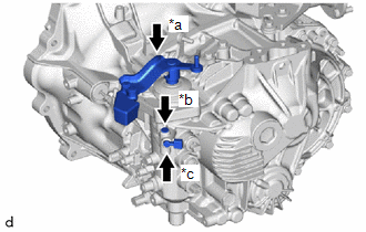
| (d) Pressing the shift and select lever shaft and shift and select lever pin, push in the shift and select lever pin and check that the shift and select lever shaft is secured at the 1st-2nd gear (the shaft comes to a stop at the position 8 mm (0.315 in.) below the N position). |
|
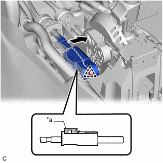
| (e) Push the slider shaft against the cam wall. NOTICE:
|
|
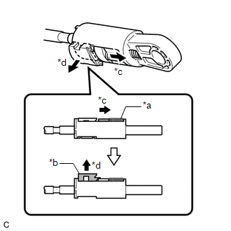
(f) Push the lock piece into the adjuster case.
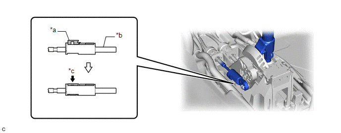
| *a | Lock Piece | *b | Adjuster Case |
| *c | Push | - | - |
NOTICE:
Securely push in the lock piece until the slider lock is engaged.
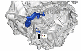
| (g) Release the shift and select lever pin that secures the shift and select lever shaft. (1) Pull the shift and select lever pin toward the front left side of the vehicle. |
|
5. INSTALL AIR CLEANER ASSEMBLY
Click here

6. INSTALL REAR CONSOLE BOX ASSEMBLY
Click here

 Removal
REMOVAL CAUTION / NOTICE / HINT HINT: When the cable is disconnected / reconnected to the auxiliary battery terminal, systems temporarily stop operating...
 Installation
INSTALLATION PROCEDURE 1. INSTALL TRANSMISSION CONTROL CABLE ASSEMBLY (a) Pass the transmission control cable assembly through the hole to the outside of the vehicle and install the transmission control cable assembly to the vehicle body with the 2 bolts...
Other information:
Toyota Yaris XP210 (2020-2026) Reapir and Service Manual: Lack of Power (Turbocharger System)
CAUTION / NOTICE / HINT HINT: The diagnosis flowchart is for lack of power due to turbocharger factors. If symptom-specific diagnosis indicates a turbocharger related problem, check using this flowchart. PROCEDURE 1. CHECK TURBOCHARGER SUB-ASSEMBLY (a) Check for oil leaks and large carbon deposits around the connecting surfaces of the turbocharger sub-assembly...
Toyota Yaris XP210 (2020-2026) Reapir and Service Manual: Steering Angle Sensor Communication Stop Mode
DESCRIPTION Detection Item Symptom Trouble Area Steering Angle Sensor Communication Stop Mode Communication stop for "Spiral cable (Steering Angle Sensor)" is indicated on the "Communication Bus Check" screen of the GTS. Click here Steering sensor branch line or connector Power source circuit of steering sensor Steering sensor ground circuit Steering sensor WIRING DIAGRAM CAUTION / NOTICE / HINT CAUTION: When performing the confirmation driving pattern, obey all speed limits and traffic laws...
Categories
- Manuals Home
- Toyota Yaris Owners Manual
- Toyota Yaris Service Manual
- Engine & Hybrid System
- Brake System Control Module "A" System Voltage System Voltage Low (C137BA2)
- How to use USB mode
- New on site
- Most important about car
Fuel Gauge
The fuel gauge shows approximately how much fuel is remaining in the tank when the ignition is switched ON. We recommend keeping the tank over 1/4 full.
