Toyota Yaris: Stop And Start / Vacuum Sensor Assembly
Components
COMPONENTS
ILLUSTRATION
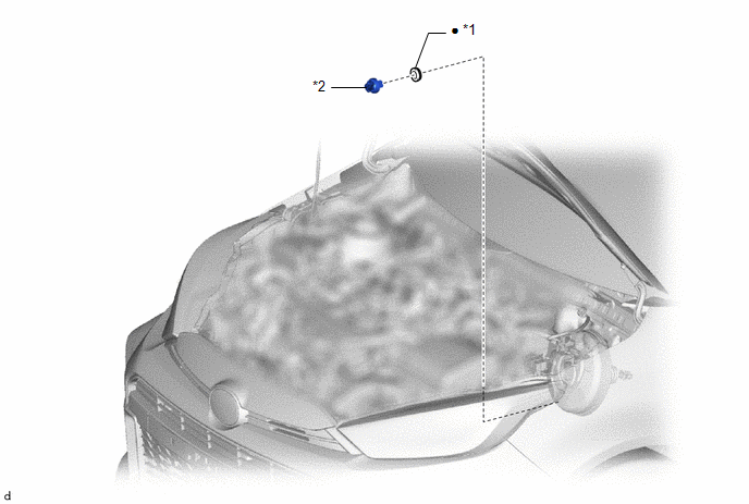
| *1 | VACUUM SENSOR GROMMET | *2 | VACUUM SENSOR ASSEMBLY |
| ● | Non-reusable part | - | - |
On-vehicle Inspection
ON-VEHICLE INSPECTION
PROCEDURE
1. INSPECT VACUUM SENSOR ASSEMBLY
(a) Connect the GTS to the DLC3.
(b) Start the engine.
(c) Turn the ignition switch off.
(d) Turn the ignition switch to ON.
(e) Turn the GTS on.
(f) Enter the following menus: Powertrain / Stop and Start / Data List / Brake Boost Pressure.
Powertrain > Stop and Start > Data List| Tester Display |
|---|
| Brake Boost Pressure |
(g) Compare the "Brake Boost Pressure" values before and after the brake pedal was depressed 5 times.
Standard:
Internal pressure changes by 20 kPa (150 mmHg, 5.91 in.Hg) or more.
HINT:
- Standard atmospheric pressure is 101 kPa (758 mmHg, 29.8 in.Hg).
- For every 100 m (328 ft.) increase in altitude, atmospheric pressure drops by 1 kPa (8 mmHg, 0.295 in.Hg).
- Atmospheric pressure varies with weather.
Removal
REMOVAL
CAUTION / NOTICE / HINT
NOTICE:
After the ignition switch is turned off, the radio and display receiver assembly records various types of memory and settings. As a result, after turning the ignition switch off, make sure to wait at least 120 seconds before disconnecting the cable from the negative (-) auxiliary battery terminal.
HINT:
When the cable is disconnected/reconnected to the auxiliary battery terminal, systems temporarily stop operating. However, each system has a function that completes learning the first time the system is used.
-
Learning completes when vehicle is driven
Effect/Inoperative Function When Necessary Procedures are not Performed
Necessary Procedures
Link
Lane tracing assist system
Drive the vehicle straight ahead at 35 km/h (22 mph) or more for 5 second or more.

Pre-collision system
Stop and start system
Drive the vehicle until stop and start control is permitted (approximately 5 to 60 minutes)

-
Learning completes when vehicle is operated normally
Effect/Inoperative Function When Necessary Procedures are not Performed
Necessary Procedures
Link
Power door lock control system
- Back door opener
Perform door unlock operation with door control switch or electrical key transmitter sub-assembly switch.

Air conditioning system
After the ignition switch is turned to ON, the servo motor standard position is recognized.
-
PROCEDURE
1. REMOVE BRAKE MASTER CYLINDER SUB-ASSEMBLY
Click here

2. REMOVE VACUUM SENSOR ASSEMBLY
| (a) Disconnect the vacuum sensor assembly connector from the vacuum sensor assembly. |
|
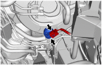
(b) Remove the vacuum sensor assembly from the brake booster assembly.
3. REMOVE VACUUM SENSOR GROMMET
(a) Remove the vacuum sensor grommet from the brake booster assembly.
Installation
INSTALLATION
PROCEDURE
1. INSTALL VACUUM SENSOR GROMMET
(a) Install the new vacuum sensor grommet to the brake booster assembly.
2. INSTALL VACUUM SENSOR ASSEMBLY
| (a) Install the vacuum sensor assembly to the brake booster assembly so that the vacuum sensor assembly is angled as shown in the illustration. |
|
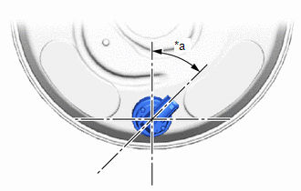
(b) Connect the vacuum sensor assembly connector to the vacuum sensor assembly.
3. INSTALL BRAKE MASTER CYLINDER SUB-ASSEMBLY
Click here
