Toyota Yaris: Vehicle Stability Control System / Terminals Of Ecu
TERMINALS OF ECU
TERMINALS OF ECU
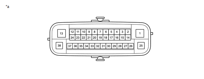
| *a | Component without harness connected (Skid Control ECU [Brake Actuator Assembly]) | - | - |
| Terminal No. (Symbol) | Terminal Description |
|---|---|
| 1 (GND2) | Pump motor ground |
| 2 | - (Not used) |
| 3 | - (Not used) |
| 4 | - (Not used) |
| 5 (STP2) | Stop light switch assembly input |
| 6 | - (Not used) |
| 7 | - (Not used) |
| 8 | - (Not used) |
| 9 | - (Not used) |
| 10 (CANL) | CAN communication line L |
| 11 | - (Not used) |
| 12 (IGR) | ECU power supply input |
| 13 (BM) | Motor relay power supply |
| 14 (SP1) | Speed signal output for speedometer |
| 15 (RR-) | Rear wheel speed RH (-) signal input |
| 16 (RR+) | Rear wheel speed RH (+) power supply output |
| 17 (FL-) | Front wheel speed LH (-) signal input |
| 18 (FL+) | Front wheel speed LH (+) power supply output |
| 19 | - (Not used) |
| 20 | - (Not used) |
| 21 | - (Not used) |
| 22 (CANH) | CAN communication line H |
| 23 | - (Not used) |
| 24 | - (Not used) |
| 25 (GND1) | Skid control ECU (brake actuator assembly) ground |
| 26 (STPO) | Stop light switch assembly output |
| 27 | - (Not used) |
| 28 (RL-) | Rear wheel speed LH (-) signal input |
| 29 (RL+) | Rear wheel speed LH (+) power supply output |
| 30 (FR-) | Front wheel speed RH (-) signal input |
| 31 (FR+) | Front wheel speed RH (+) power supply output |
| 32 | - (Not used) |
| 33 (CSW) | VSC OFF switch (combination switch assembly) input |
| 34 | - (Not used) |
| 35 (STP) | Stop light switch assembly input |
| 36 (CA2H) | CAN communication line H |
| 37 (CA2L) | CAN communication line L |
| 38 (+BS) | Solenoid relay power supply |
TERMINAL INSPECTION
(a) Disconnect the A108 connector and measure the voltage or resistance on the wire harness side.
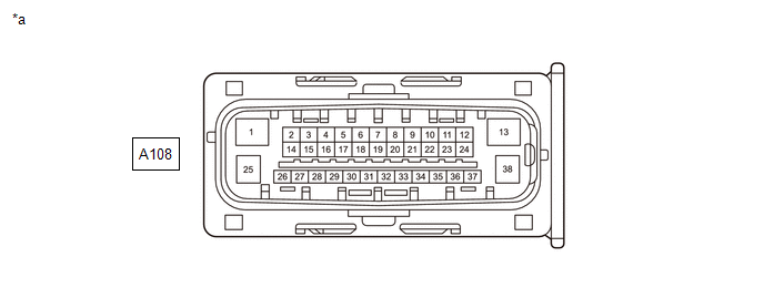
| *a | Front view of wire harness connector (to Skid Control ECU [Brake Actuator Assembly]) | - | - |
HINT:
Voltage cannot be measured with the connector connected to the skid control ECU (brake actuator assembly) as the connector is watertight.
| Terminal No. (Symbol) | Terminal Description | Condition | Specified Condition |
|---|---|---|---|
| A108-1 (GND2) - Body ground | Pump motor ground | Always | Below 1 Ω |
| A108-5 (STP2) - Body ground | Stop light switch assembly input | Brake pedal depressed → released | 8 to 14 V → Below 1.5 V |
| A108-12 (IGR) - Body ground | ECU power supply input | Ignition switch ON | 10.5 to 16 V |
| A108-13 (BM) - Body ground | Motor relay power supply | Always | 11 to 14 V |
| A108-14 (SP1) - Body ground | Speed signal output for speedometer | Ignition switch ON | 11 to 14 V |
| A108-25 (GND1) - Body ground | Skid control ECU (brake actuator assembly) ground | Always | Below 1 Ω |
| A108-26 (STPO) - Body ground | Stop light switch assembly output | Ignition switch ON | 11 to 14 V |
| A108-33 (CSW) - Body ground | VSC OFF switch (combination switch assembly) input | VSC OFF switch (combination switch assembly) pressed and held → released | Below 1 Ω → 10 kΩ or higher |
| A108-35 (STP) - Body ground | Stop light switch assembly input | Stop light switch assembly on → off (Brake pedal depressed → released) | 8 to 14 V → Below 1.5 V |
| A108-38 (+BS) - Body ground | Solenoid relay power supply | Always | 11 to 14 V |
 Diagnosis System
DIAGNOSIS SYSTEM DESCRIPTION When troubleshooting a vehicle with the diagnosis system, the only difference from the usual troubleshooting procedure is connecting the GTS to the vehicle and reading various data output from the vehicle's skid control ECU (brake actuator assembly)...
 Dtc Check / Clear
DTC CHECK / CLEAR DTC CHECK (a) Operate the GTS to read the DTCs. Chassis > Brake > Trouble Codes (b) Check the details of the DTCs. NOTICE:
Make sure to clear the DTCs after repair...
Other information:
Toyota Yaris XP210 (2020-2026) Reapir and Service Manual: Data List / Active Test
DATA LIST / ACTIVE TEST HINT: Using the GTS to read the Data List allows the values or states of switches, sensors, actuators and other items to be read without removing any parts. This non-intrusive inspection can be very useful because intermittent conditions or signals may be discovered before parts or wiring is disturbed...
Toyota Yaris XP210 (2020-2026) Reapir and Service Manual: ABS Warning Light Remains ON
DESCRIPTION This procedure is for troubleshooting when the ABS warning light remains on but no DTCs are output. The skid control ECU (brake actuator assembly) controls the ABS warning light in the combination meter assembly via CAN communication. CAUTION / NOTICE / HINT NOTICE: After replacing the skid control ECU (brake actuator assembly), perform "Calibration"...
Categories
- Manuals Home
- Toyota Yaris Owners Manual
- Toyota Yaris Service Manual
- Headlights
- How to connect USB port/Auxiliary jack
- Fuse Panel Description
- New on site
- Most important about car
Fuel-Filler Lid and Cap
WARNING
When removing the fuel-filler cap, loosen the cap slightly and wait for any hissing to stop, then remove it
Fuel spray is dangerous. Fuel can burn skin and eyes and cause illness if ingested. Fuel spray is released when there is pressure in the fuel tank and the fuel-filler cap is removed too quickly.