Toyota Yaris: Smart Key System (for Start Function) / Terminals Of Ecu
TERMINALS OF ECU
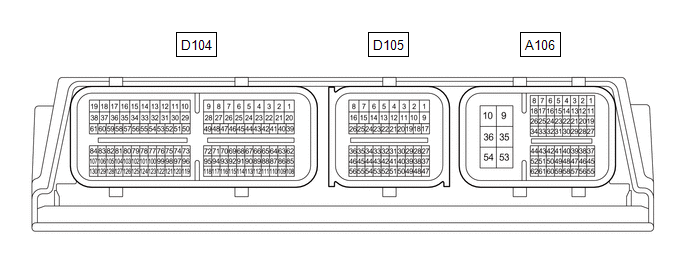
CHECK CERTIFICATION ECU (SMART KEY ECU ASSEMBLY)
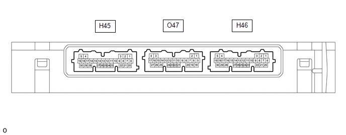
(a) Disconnect the H45 and H46 certification ECU (smart key ECU assembly) connectors.
(b) Measure the resistance and voltage according to the value(s) in the table below.
HINT:
Measure the values on the wire harness side with the connector disconnected.
| Tester Connection | Terminal Description | Condition | Specified Condition | Related Data List Item/DTC |
|---|---|---|---|---|
| H45-15 (NE) - Body ground | Engine speed signal | Always | 10 kΩ or higher | Power Source Control
|
| H46-6 (+B) - H46-29 (E) | Power source | Always | 11 to 14 V | - |
| H45-22 (CUTB) - Body ground | Dark current cut pin*1 | Always | 11 to 14 V | - |
| H46-29 (E) - Body ground | GND | Always | Below 1 Ω | - |
| H46-23 (SSW3) - Body ground | SSW3 contact signal | Engine switch pushed → Engine switch not pushed | Below 15 Ω → 10 kΩ or higher | Power Source Control
|
| H46-27 (SSW2) - Body ground | SSW2 contact signal | Engine switch pushed → Engine switch not pushed | Below 15 Ω → 10 kΩ or higher | Power Source Control
|
| H46-19 (SSW1) - Body ground | SSW1 contact signal | Engine switch pushed → Engine switch not pushed | Below 15 Ω → 10 kΩ or higher | Power Source Control
|
| H45-13 (SPD) - Body ground | Vehicle speed signal | Always | 30 kΩ or higher | Power Source Control
|
- *1: In order to prevent the vehicle auxiliary battery from being depleted when the vehicle is shipped long distances, a fuse that cuts unnecessary electrical load while the vehicle is being shipped is installed in the circuit. If the fuse is removed, the circuit becomes open. If the fuse that is between the vehicle auxiliary battery and terminal CUTB is removed and the circuit is open, the certification ECU (smart key ECU assembly) changes to a certain control mode (example: the transmission of radio waves every 0.25 seconds, which form the detection area, stops).
(c) Connect the H45 and H46 certification ECU (smart key ECU assembly) connectors.
(d) Measure the voltage and resistance, and check for pulses according to the value(s) in the table below.
| Tester Connection | Terminal Description | Condition | Specified Condition | Related Data List Item/DTC |
|---|---|---|---|---|
| H45-3 (STA) - H46-29 (E) | When starting the engine, this monitors the voltage sent from terminal STAR to the starter relay to judge whether the engine is "being started". | Engine switch pressed and held with clutch pedal depressed (starter on) → Approximately 1 second after engine switch released (starter off) | 6 V → 1.0 V or less | - |
| H45-10 (STAR) - H46-29 (E) | Outputs voltage to the starter relay
HINT: When Hi is selected, a start request signal (STAR) will not be output even though a start request signal (STSW) is input. | Engine switch pressed and held with clutch pedal depressed (starter on) → Approximately 1 second after engine switch released (starter off) | 6 V → 1.0 V or less | - |
| H45-15 (NE) - Body ground | Engine speed signal | Idling (engine warmed up) | Pulse generation (See waveform 5) | Power Source Control
|
| H46-11 (SLP) - H46-29 (E) | Steering lock position signal | Steering locked → Steering unlocked | 11 to 14 V → 1.5 V or less | Power Source Control
|
| H46-24 (SLR+) - H46-29 (E) | Steering lock motor operation command signal (Steering lock motor operation permission signal sent from the certification ECU (smart key ECU assembly)) | When a door is opened, the steering lock motor will be operated if all of the following conditions are met:
| Pulse generation (See waveform 1) | - |
| H46-8 (LIN) - H46-29 (E) | LIN communication line | Ignition switch ON | Pulse generation | Smart Key
|
| H46-23 (SSW3) - H46-29 (E) | SSW3 contact signal | Engine switch not pushed → Engine switch pushed | 9 V or higher → 1 V or less | Power Source Control
|
| H46-27 (SSW2) - H46-29 (E) | SSW2 contact signal | Engine switch not pushed → Engine switch pushed | 9 V or higher → 1 V or less | Power Source Control
|
| H46-19 (SSW1) - H46-29 (E) | SSW1 contact signal | Engine switch not pushed → Engine switch pushed | 9 V or higher → 1 V or less | Power Source Control
|
| H46-21 (ACCD) - H46-29 (E) | ACC signal | Ignition switch off → Ignition switch ACC | 1 V or less → 8.5 V or higher | Power Source Control
|
| H45-11 (IGRD) - H46-29 (E) | IG signal | Ignition switch off → Ignition switch ON | 1 V or less → 9 V or higher | Power Source Control
|
| H45-24 (IGPD) - H46-29 (E) | IG signal | Ignition switch off → Ignition switch ON | 1 V or less → 9 V or higher | Power Source Control
|
| H45-13 (SPD) - H46-29 (E) | Vehicle speed signal | Vehicle being driven at approx. 5 km/h (3 mph) | Pulse generation (See waveform 2) | Power Source Control
|
| H46-4 (CLG5) - H46-29 (E) | Output to No. 1 indoor electrical key antenna assembly (front floor) | Procedure:
| Pulse generation (See waveform 3) | - |
| H46-5 (CG5B) - H46-29 (E) | Output to No. 1 indoor electrical key antenna assembly (front floor) (terminal on opposite side of component from CLG5 output terminal) | Procedure:
| Pulse generation (See waveform 3) | - |
| O47-10 (CLG7) - H46-29 (E) | Output to No. 2 indoor electrical key antenna assembly (rear floor) | Procedure:
| Pulse generation (See waveform 3) | - |
| O47-9 (CG7B) - H46-29 (E) | Output to No. 2 indoor electrical key antenna assembly (rear floor) (terminal on opposite side of component from CLG7 output terminal) | Procedure:
| Pulse generation (See waveform 3) | - |
| H46-30 (AGND) - Body ground | Transponder key amplifier ground | Always | Below 1 Ω | - |
| H46-12 (ANT1) - H46-30 (AGND) | Signal input / output from transponder key coil (transponder key coil built into engine switch) | Ignition switch off, electrical key transmitter sub-assembly not in cabin, within 30 seconds of engine switch pressed | Pulse generation (See waveform 4) | Smart Key
|
| H46-13 (ANT2) - H46-30 (AGND) | Signal input / output from transponder key coil (transponder key coil built into engine switch) | Ignition switch off, electrical key transmitter sub-assembly not in cabin, within 30 seconds of engine switch pressed | Pulse generation (See waveform 4) | |
| H46-25 (IND) - H46-29 (E) | Security indicator output | Ignition switch off → ON | Pulse generation → Below 2 V | - |
HINT:
- The waveform of the steering lock actuator motor stopped can be checked without performing any particular operation.
-
The waveform of the steering lock actuator motor operating can be checked if either of the following operations is performed:
- To unlock the steering, bring the electrical key transmitter sub-assembly into the cabin and turn the ignition switch to ACC or ON.
- To lock the steering, open a door with the ignition switch off.
- *1: While the engine is cranking, the auxiliary battery voltage may drop to approximately 6 V.
(e) Using an oscilloscope, check the waveform of the ECU.
NOTICE:
The oscilloscope waveform shown in the illustration is an example for reference only. Noise, chattering, etc. are not shown.
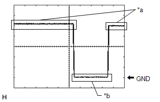
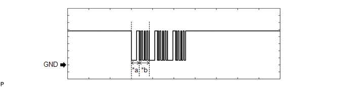
(1) Waveform 1
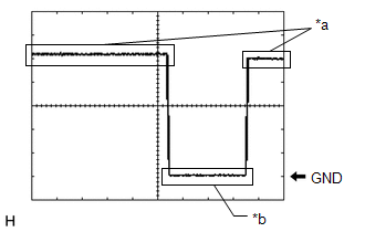
| *a | Steering lock motor not operating |
| *b | Steering lock motor operating |
| Item | Content |
|---|---|
| Tester Connection | H46-24 (SLR+) - H46-29 (E) |
| Tool Setting | 2 V/DIV., 200 ms./DIV. |
| Condition | When a door is opened, the steering lock motor will be operated if all of the following conditions are met:
|
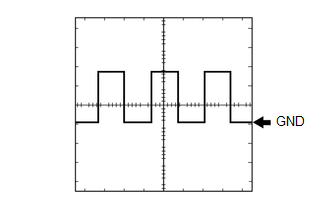
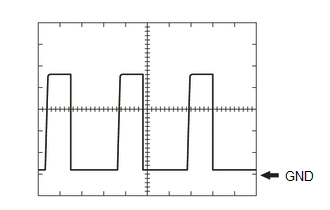
(2) Waveform 2
 Measurement Condition
 | Item | Content |
|---|---|
| Tester Connection | H45-13 (SPD) - H46-29 (E) |
| Tool Setting | 5 V/DIV., 20 ms./DIV. |
| Condition | Vehicle being driven at approx. 5 km/h (3 mph) |
HINT:
The wavelength becomes shorter as the vehicle speed increases.
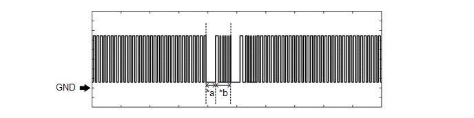
(3) Waveform 3
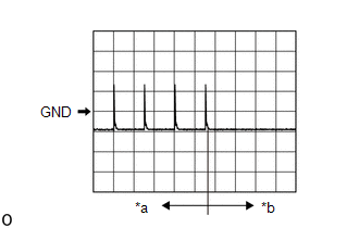
| *a | For 30 seconds after any door closed |
| *b | After 30 seconds or more have elapsed since any door closed |
| Item | Content |
|---|---|
| Tester Connection | H46-4 (CLG5) - H46-29 (E) H46-5 (CG5B) - H46-29 (E) O47-10 (CLG7) - H46-29 (E) O47-9 (CG7B) - H46-29 (E) |
| Tool Setting | 5 V/DIV., 500 ms./DIV. |
| Condition | Procedure:
|
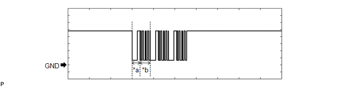
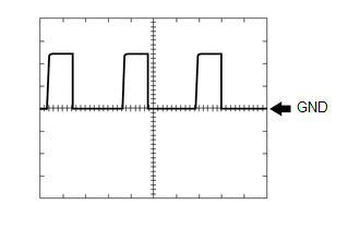
(4) Waveform 4
 Measurement Condition
 | Item | Content |
|---|---|
| Tester Connection | H46-12 (ANT1) - H46-30 (AGND) H46-13 (ANT2) - H46-30 (AGND) |
| Tool Setting | 20 V/DIV., 200 ms./DIV. |
| Condition | Ignition switch off, electrical key transmitter sub-assembly not in cabin, within 30 seconds of engine switch pressed |
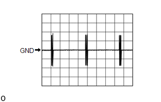
(5) Waveform 5
 Measurement Condition
 | Item | Content |
|---|---|
| Tester Connection | H45-15 (NE) - Body ground |
| Tool Setting | 2 V/DIV., 2 ms./DIV. |
| Condition | Idling (engine warmed up) |
HINT:
The wavelength becomes shorter as the engine speed increases.
CHECK STEERING LOCK ECU (STEERING LOCK ACTUATOR OR UPPER BRACKET ASSEMBLY)

(a) Disconnect the H71 steering lock ECU (steering lock actuator or upper bracket assembly) connector.
(b) Measure the voltage and resistance according to the value(s) in the table below.
HINT:
Measure the values on the wire harness side with the connector disconnected.
| Terminal No. (Symbol) | Terminal Description | Condition | Specified Condition | Related Data List Item/DTC |
|---|---|---|---|---|
| H71-1 (GND) - Body ground | Ground | Always | Below 1 Ω | - |
| H71-7 (B) - Body ground | Constant power supply | Ignition switch off | 11 to 14 V | - |
(c) Connect the H71 steering lock ECU (steering lock actuator or upper bracket assembly) connector.
(d) Measure the voltage, and check for pulses according to the value(s) in the table below.
| Terminal No. (Symbol) | Terminal Description | Condition | Specified Condition | Related Data List Item/DTC |
|---|---|---|---|---|
| H71-3 (IGE) - H71-1 (GND) | Steering lock motor operation permission signal (motor operation permission signal supplied by certification ECU (smart key ECU assembly)) | Steering lock motor operating when all conditions met, and then door opened:
| Pulse generation (See waveform 1) | Smart Key
|
| H71-4 (SLP1) - H71-1 (GND) | Steering lock bar position signal (signal output from steering unlock sensor) | Steering locked → unlocked | 11 to 14 V → Below 1.5 V | Smart Key
|
| H71-5 (LIN) - H71-1 (GND) | LIN communication line | Ignition switch ON | Pulse generation | Smart Key
|
| H71-6 (SLA) - H71-1 (GND) | Steering lock motor operation permission signal (motor operation permission signal supplied by certification ECU (smart key ECU assembly)) | Ignition switch off → ON | Below 1 V → 11 to 14 V | - |
HINT:
- There is 1 motor and 2 sensors built into the steering lock actuator or upper bracket assembly.
- When taking measurements when the lock motor is stopped, it is not necessary to perform any operations.
-
In order to take measurements when the lock motor is operating, perform either of the following operations:
- To unlock the steering, carry the key and turn the ignition switch to ACC or ON.
- To lock the steering, turn the ignition switch off and then open a door.
(e) Using an oscilloscope, check the waveform of the ECU.
NOTICE:
The oscilloscope waveform shown in the illustration is an example for reference only. Noise, chattering, etc. are not shown.
Waveform 1
| *a | Steering lock motor not operating |
| *b | Steering lock motor operating |
| Item | Content |
|---|---|
| Tester Connection | H71-3 (IGE) - H71-1 (GND) |
| Tool Setting | 2 V/DIV., 200 ms./DIV. |
| Condition | Steering lock motor operating when all conditions met, and then door opened:
|
CHECK ID CODE BOX (IMMOBILISER CODE ECU)

(a) Disconnect the H67 ID code box (immobiliser code ECU) connector.
(b) Measure the voltage and resistance according to the value(s) in the table below.
HINT:
Measure the values on the wire harness side with the connector disconnected.
| Tester Connection | Terminal Description | Condition | Specified Condition | Related Data List Item |
|---|---|---|---|---|
| H67-1 (+B) - Body ground | Power source | Ignition switch off | 11 to 14 V | - |
| H67-5 (GND) - Body ground | Ground | Always | Below 1 Ω |
(c) Reconnect the H67 ID code box (immobiliser code ECU) connector.
(d) Measure the voltage and check for pulses according to the value(s) in the table below.
| Tester Connection | Terminal Description | Condition | Specified Condition | Related Data List Item |
|---|---|---|---|---|
| H67-3 (EFII) - H67-5 (GND) | EFI communication input (Signal input from ECM to ID code box (immobiliser code ECU)) | Ignition switch off | 11 to 14 V | Smart Key
|
| H67-3 (EFII) - H67-5 (GND) | EFI communication input (Signal input from ECM to ID code box (immobiliser code ECU)) | Within 3 seconds of engine start or within 3 seconds of ignition switch turned to ON after cable disconnected and reconnected to auxiliary battery | Pulse generation (See waveform 1) | |
| H67-4 (EFIO) - H67-5 (GND) | EFI communication output (Signal output from ID code box (immobiliser code ECU) to ECM) | Ignition switch off | Below 1 V | |
| H67-4 (EFIO) - H67-5 (GND) | EFI communication output (Signal output from ID code box (immobiliser code ECU) to ECM) | Within 3 seconds of engine start or within 3 seconds of ignition switch turned to ON after cable disconnected and reconnected to auxiliary battery | Pulse generation (See waveform 2) | |
| H67-2 (LIN1) - H67-5 (GND) | LIN communication line | Ignition switch ON | Pulse generation | Smart Key
|
(e) Using an oscilloscope, check the waveform.
NOTICE:
The waveform shown in the illustration is an example for reference only. Noise, chattering, etc. are not shown.
(1) Waveform 1
| *a | Approximately 160 ms. | *b | Approximately 270 ms. |
| Item | Content |
|---|---|
| Tester Connection | H67-3 (EFII) - H67-5 (GND) |
| Tool Setting | 2 V/DIV., 500 ms./DIV. |
| Condition | Within 3 seconds of engine start or within 3 seconds of ignition switch turned to ON after cable disconnected and reconnected to auxiliary battery |
(2) Waveform 2

| *a | Approximately 160 ms. | *b | Approximately 270 ms. |
| Item | Content |
|---|---|
| Tester Connection | H67-4 (EFIO) - H67-5 (GND) |
| Tool Setting | 2 V/DIV., 500 ms./DIV. |
| Condition | Within 3 seconds of engine start or within 3 seconds of ignition switch turned to ON after cable disconnected and reconnected to auxiliary battery |
CHECK ECM
(a) Measure the voltage and resistance, and check for pulses according to the value(s) in the table below.
| Terminal No. (Symbol) | Terminal Description | Condition | Specified Condition | Related Data List Item/DTC |
|---|---|---|---|---|
| A106-13 (IGR) - A106-10 (E1) | Ignition power supply | Ignition switch ON | 11 to 14 V | - |
| A106-1 (BATT) - A106-10 (E1) | +B power supply | Always | 11 to 14 V | - |
| A106-10 (E1) - Body ground | Ground | Always | Below 1 Ω | - |
| A106-47 (IMO) - A106-10 (E1) | EFI communication input (Signal input from ECM to ID code box (immobiliser code ECU)) | Ignition switch off | 11 to 14 V | Smart Key
|
| EFI communication input (Signal input from ECM to ID code box (immobiliser code ECU)) | Within 3 seconds of engine start or within 3 seconds of ignition switch turned to ON after cable disconnected and reconnected to auxiliary battery | Pulse generation (See waveform 1) | ||
| A106-61 (IMI) - A106-10 (E1) | EFI communication input (Signal output from ID code box (immobiliser code ECU) to ECM) | Ignition switch off | 1 V or less | |
| EFI communication input (Signal output from ID code box (immobiliser code ECU) to ECM) | Ignition switch turned to ON using registered electrical key transmitter sub-assembly | Pulse generation (See waveform 2) | ||
| A106-16 (NEO) - A106-10 (E1) | Engine speed signal | Idling (engine warmed up) | Pulse generation (See waveform 3) | Power Source Control
|
| A106-30 (STA) - A106-10 (E1) | When starting the engine, this monitors the voltage sent from terminal STAR to the starter relay to judge whether the engine is "being started". | Engine is cranking | 6 V or higher | - |
| A106-23 (NSW) - A106-10 (E1) | Clutch start switch signal | Ignition switch ON (Clutch pedal fully depressed) | Below 1.5 V | - |
| Ignition switch ON (Clutch pedal released) | 11 to 14 V | - |
(b) Using an oscilloscope, check the waveform.
NOTICE:
The waveform shown in the illustration is an example for reference only. Noise, chattering, etc. are not shown.
(1) Waveform 1 (Reference)
| *a | Approximately 160 ms. | *b | Approximately 270 ms. |
| Item | Content |
|---|---|
| Tester Connection | A106-47 (IMO) - A106-10 (E1) |
| Tool Setting | 2 V/DIV., 500 ms./DIV. |
| Condition | Within 3 seconds of engine start or within 3 seconds of ignition switch turned to ON after cable disconnected and reconnected to auxiliary battery |
(2) Waveform 2 (Reference)
| *a | Approximately 160 ms. | *b | Approximately 270 ms. |
| Item | Content |
|---|---|
| Tester Connection | A106-61 (IMI) - A106-10 (E1) |
| Tool Setting | 2 V/DIV., 500 ms./DIV. |
| Condition | Ignition switch turned to ON using registered electrical key transmitter sub-assembly |
(3) Waveform 3
 Measurement Condition
 | Item | Content |
|---|---|
| Tester Connection | A106-16 (NEO) - A106-10 (E1) |
| Tool Setting | 5 V/DI., 20 ms./DIV. |
| Condition | Idling (engine warmed up) |
HINT:
The wavelength becomes shorter as the engine speed increases.
CHECK ENGINE SWITCH

(a) Measure the voltage and resistance, and check for pulses according to the value(s) in the table below.
| Terminal No. (Symbol) | Terminal Description | Condition | Specified Condition | Related Data List Item/DTC |
|---|---|---|---|---|
| H68-3 (GND) - Body ground | Transponder key amplifier ground | Always | Below 1 Ω | - |
| H68-11 (SS3) - H68-3 (GND) | SS3 contact signal HINT: Backup for SS1. Behaves the same way as SS1. | Engine switch not pushed → Engine switch pushed | 9 V or higher → Below 1 V | Power Source Control
|
| H68-6 (SS2) - H68-3 (GND) | SS2 contact signal HINT: Backup for SS1. Behaves the same way as SS1. | Engine switch not pushed → Engine switch pushed | 9 V or higher → Below 1 V | Power Source Control
|
| H68-12 (SS1) - H68-3 (GND) | SS1 contact signal | Engine switch not pushed → Engine switch pushed | 9 V or higher → Below 1 V | Power Source Control
|
(b) Check for pulses according to the value(s) in the table below.
| Terminal No. (Symbol) | Terminal Description | Condition | Specified Condition | Related Data List Item/DTC |
|---|---|---|---|---|
| H68-1 (ANT1) - H68-3 (GND) | Signal input / output from transponder key coil (transponder key coil built into engine switch) | Ignition switch off, electrical key transmitter sub-assembly not in cabin, within 30 seconds of engine switch pressed | Pulse generation (See waveform 1) | Smart Key
|
| H68-7 (ANT2) - H68-3 (GND) | Signal input / output from transponder key coil (transponder key coil built into engine switch) | Ignition switch off, electrical key transmitter sub-assembly not in cabin, within 30 seconds of engine switch pressed | Pulse generation (See waveform 1) |
(c) Using an oscilloscope, check the waveform.
NOTICE:
The waveform shown in the illustration is an example for reference only. Noise, chattering, etc. are not shown.
(1) Waveform 1 (Reference)
 Measurement Condition
 | Item | Content |
|---|---|
| Tester Connection | H68-1 (ANT1) - H68-3 (GND) H68-7 (ANT2) - H68-3 (GND) |
| Tool Setting | 20 V/DIV., 200 ms./DIV. |
| Condition | Ignition switch off, electrical key transmitter sub-assembly not in cabin, within 30 seconds of engine switch pressed |
SMART KEY SYSTEM (for Entry Function)
Click here

 Problem Symptoms Table
PROBLEM SYMPTOMS TABLE HINT:
Use the table below to help determine the cause of problem symptoms. If multiple suspected areas are listed, the potential causes of the symptoms are listed in order of probability in the "Suspected Area" column of the table...
 Dtc Check / Clear
DTC CHECK / CLEAR NOTICE:
When DTC is output, be sure to confirm and record.
DTCs may have been stored due to problems unrelated to the steering lock function...
Other information:
Toyota Yaris XP210 (2020-2026) Reapir and Service Manual: Reassembly
REASSEMBLY CAUTION / NOTICE / HINT NOTICE: When using a vise, place aluminum plates between the part and vise. When using a vise, do not overtighten it. HINT: Use the same procedure for the RH side and LH side. The following procedure is for the LH side...
Toyota Yaris XP210 (2020-2026) Reapir and Service Manual: Check Mode Procedure
CHECK MODE PROCEDURE HINT: Compared to normal mode, check mode is more sensitive to malfunctions. Therefore, check mode can detect malfunctions that cannot be detected in normal mode. NOTICE: All of the stored DTCs and Freeze Frame Data are cleared if: 1) the ECM is changed from normal mode to check mode or vice versa; or 2) the ignition switch is turned from ON to ACC or off while in check mode...
Categories
- Manuals Home
- Toyota Yaris Owners Manual
- Toyota Yaris Service Manual
- Power Integration No.1 System Missing Message (B235287,B235587,B235787-B235987)
- G16e-gts (engine Mechanical)
- Fuse Panel Description
- New on site
- Most important about car
Front Seat Belt Pretensioners
The front seat belt pretensioners are designed to deploy in moderate or severe frontal, near frontal collisions.
In addition, the pretensioners operate when a side collision or a rollover accident is detected. The pretensioners operate differently depending on what types of air bags are equipped. For more details about the seat belt pretensioner operation, refer to the SRS Air Bag Deployment Criteria.