Toyota Yaris: Window Defogger System / Terminals Of Ecu
TERMINALS OF ECU
CHECK MAIN BODY ECU (MULTIPLEX NETWORK BODY ECU) AND INSTRUMENT PANEL JUNCTION BLOCK ASSEMBLY
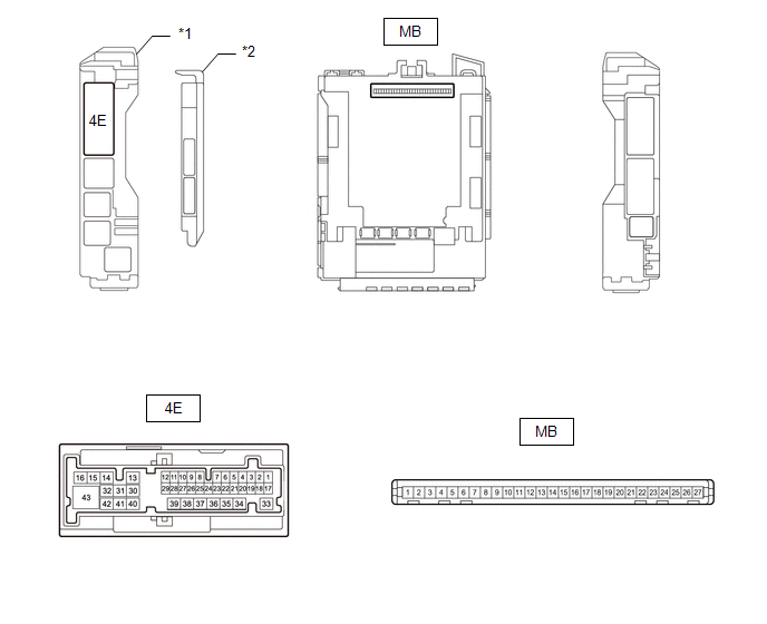
| *1 | Power Distribution Box Assembly | *2 | Main Body ECU (Multiplex Network Body ECU) |
(a) Remove the main body ECU (multiplex network body ECU) from the power distribution box assembly.
Click here
.gif)
(b) Connect the power distribution box assembly connectors.
(c) Measure the resistance and voltage according to the value(s) in the table below.
| Terminal No. (Symbol) | Terminal Description | Condition | Specified Condition |
|---|---|---|---|
| MB-26 (BECU) - Body ground | Auxiliary battery power supply | Ignition switch off | 11 to 14 V |
| MB-27 (IGR) - Body ground | Ignition power supply (IG signal) | Ignition switch off → ON | Below 1 V → 11 to 14 V |
| MB-13 (GND1) - Body ground | Ground | Always | Below 1 Ω |
(d) Install to the power distribution box assembly the main body ECU (multiplex network body ECU).
Click here
(e) Measure the voltage according to the value(s) in the table below
| Terminal No. (Symbol) | Terminal Description | Condition | Specified Condition |
|---|---|---|---|
| 4E-43 - Body ground | Rear window defogger signal (output) | Rear window defogger switch off | Below 1 V |
| Rear window defogger switch on | 11 to 14 V |
AIR CONDITIONING AMPLIFIER ASSEMBLY
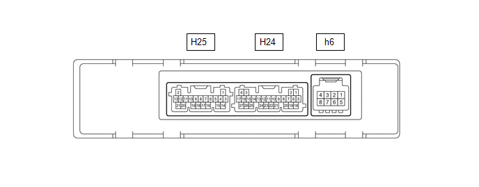
(a) Disconnect the H24 air conditioning amplifier assembly connector.
(b) Measure the resistance and voltage according to the value(s) in the table below.
| Terminal No. (Symbol) | Terminal Description | Condition | Specified Condition |
|---|---|---|---|
| H24-5 (B) - H24-17 (GND) | Power source | Ignition switch off | 11 to 14 V |
| H24-6 (IG+) - H24-17 (GND) | Power source (IG) | Ignition switch off | Below 1 V |
| Ignition switch ON | 11 to 14 V | ||
| H24-17 (GND) - Body ground | Ground | Always | Below 1 Ω |
(c) Connect the H24 air conditioning amplifier assembly connectors.
(d) Measure the pulses according to the value(s) in the table below.
| Terminal No. (Symbol) | Terminal Description | Condition | Specified Condition |
|---|---|---|---|
| H24-1 (CANL) - Body ground | CAN communication line | Ignition switch ON | Pulse generation |
| H24-2 (CANH) - Body ground | CAN communication line | Ignition switch ON | Pulse generation |
| H24-7 (LIN1) - Body ground | LIN communication line | Ignition switch ON | Pulse generation |
 Problem Symptoms Table
PROBLEM SYMPTOMS TABLE HINT:
Inspect the fuses and relays related to this system before inspecting the suspected areas below.
Use the table below to help determine the cause of problem symptoms...
 Diagnosis System
DIAGNOSIS SYSTEM CHECK DLC3 (a) Check the DLC3. Click here
INSPECT AUXILIARY BATTERY VOLTAGE (a) Measure the auxiliary battery voltage with ignition switch off...
Other information:
Toyota Yaris XP210 (2020-2026) Reapir and Service Manual: Vacuum Sensor
ComponentsCOMPONENTS ILLUSTRATION *1 E.F.I. VACUUM SENSOR ASSEMBLY *2 VACUUM HOSE *3 NO. 1 ENGINE COVER SUB-ASSEMBLY - - N*m (kgf*cm, ft.*lbf): Specified torque - - On-vehicle InspectionON-VEHICLE INSPECTION PROCEDURE 1...
Toyota Yaris XP210 (2020-2026) Reapir and Service Manual: Certification Ecu
ComponentsCOMPONENTS ILLUSTRATION *1 CERTIFICATION ECU (SMART KEY ECU ASSEMBLY) - - RemovalREMOVAL CAUTION / NOTICE / HINT The necessary procedures (adjustment, calibration, initialization, or registration) that must be performed after parts are removed, installed, or replaced during the certification ECU (smart key ECU assembly) removal/installation are shown below...
Categories
- Manuals Home
- Toyota Yaris Owners Manual
- Toyota Yaris Service Manual
- Removal
- How to connect USB port/Auxiliary jack
- Battery Monitor Module General Electrical Failure (P058A01)
- New on site
- Most important about car
Refueling
Before refueling, close all the doors, windows, and the liftgate/trunk lid, and switch the ignition OFF.
To open the fuel-filler lid, pull the remote fuel-filler lid release.
