Toyota Yaris: Lin Communication System / Terminals Of Ecu
TERMINALS OF ECU
CHECK POWER DISTRIBUTION BOX ASSEMBLY AND MAIN BODY ECU (MULTIPLEX NETWORK BODY ECU)
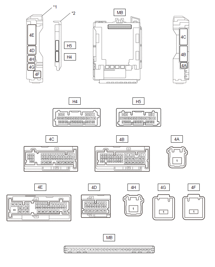
| *1 | POWER DISTRIBUTION BOX ASSEMBLY | *2 | MAIN BODY ECU (MULTIPLEX NETWORK BODY ECU) |
(a) Remove main body ECU (multiplex network body ECU).
Click here

(b) Measure the voltage and resistance according to the value(s) in the table below.
HINT:
Measure the values on the wire harness side with the connectors disconnected.
| Terminal No. (Symbol) | Terminal Description | Switch Condition | Specified Condition |
|---|---|---|---|
| MB-13 (GND1) - Body ground | Ground | Always | Below 1 Ω |
| MB-26 (BECU) - Body ground | Auxiliary battery power supply | Ignition switch off | 11 to 14 V |
| MB-27 (IGR) - Body ground | IGR power supply | Ignition switch ON | 11 to 14 V |
| Ignition switch off | Below 1 V |
(c) Install main body ECU (multiplex network body ECU) connector.
Click here

(d) Check for pulses according to the value(s) in the table below.
| Terminal No. (Symbol) | Terminal Description | Switch Condition | Specified Condition |
|---|---|---|---|
| 4E-17 - Body ground | LIN communication line | Ignition switch ON | Pulse generation |
CHECK FRONT POWER WINDOW REGULATOR MOTOR ASSEMBLY (DRIVER DOOR)
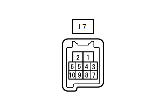
(a) Disconnect the L7 front power window regulator motor assembly (driver door) connector.
(b) Measure the voltage and resistance according to the value(s) in the table below.
HINT:
Measure the values on the wire harness side with the connector disconnected.
| Terminal No. (Symbol) | Terminal Description | Switch Condition | Specified Condition |
|---|---|---|---|
| L7-2 (B) - Body ground | Auxiliary battery power supply | Ignition switch off | 11 to 14 V |
| L7-1 (GND) - Body ground | Ground | Always | Below 1 Ω |
(c) Reconnect the L7 front power window regulator motor assembly (driver door) connector.
(d) Check for pulses according to the value(s) in the table below.
| Terminal No. (Symbol) | Terminal Description | Switch Condition | Specified Condition |
|---|---|---|---|
| L7-9 (LIN) - Body ground | LIN communication line | Ignition switch ON | Pulse generation |
CHECK FRONT POWER WINDOW REGULATOR MOTOR ASSEMBLY (FRONT PASSENGER DOOR)
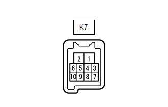
(a) Disconnect the K7 front power window regulator motor assembly (front passenger door) connector.
(b) Measure the voltage and resistance according to the value(s) in the table below.
HINT:
Measure the values on the wire harness side with the connector disconnected.
| Terminal No. (Symbol) | Terminal Description | Switch Condition | Specified Condition |
|---|---|---|---|
| K7-2 (B) - Body ground | Auxiliary battery power supply | Ignition switch off | 11 to 14 V |
| K7-1 (GND) - Body ground | Ground | Always | Below 1 Ω |
(c) Reconnect the K7 front power window regulator motor assembly (front passenger door) connector.
(d) Check for pulses according to the value(s) in the table below.
| Terminal No. (Symbol) | Terminal Description | Switch Condition | Specified Condition |
|---|---|---|---|
| K7-9 (LIN) - Body ground | LIN communication line | Ignition switch ON | Pulse generation |
CHECK MULTIPLEX NETWORK MASTER SWITCH ASSEMBLY

(a) Disconnect the L13 multiplex network master switch assembly connector.
(b) Measure the voltage and resistance according to the value(s) in the table below.
HINT:
Measure the values on the wire harness side with the connector disconnected.
| Terminal No. (Symbol) | Terminal Description | Switch Condition | Specified Condition |
|---|---|---|---|
| L13-11 (B) - Body ground | Auxiliary battery power supply | Ignition switch off | 11 to 14 V |
| L13-12 (GND) - Body ground | Ground | Always | Below 1 Ω |
(c) Reconnect the L13 multiplex network master switch assembly connector.
(d) Check for pulses according to the value(s) in the table below.
| Terminal No. (Symbol) | Terminal Description | Switch Condition | Specified Condition |
|---|---|---|---|
| L13-17 (LIN1) - Body ground | LIN communication line | Ignition switch ON | Pulse generation |
| L13-16 (LIN2) - Body ground | LIN communication line | Ignition switch ON | Pulse generation |
CHECK CERTIFICATION ECU (SMART KEY ECU ASSEMBLY)
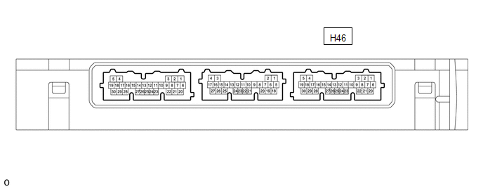
(a) Disconnect the H46 certification ECU (smart key ECU assembly) connector.
(b) Measure the voltage and resistance according to the value(s) in the table below.
HINT:
Measure the values on the wire harness side with the connector disconnected.
| Terminal No. (Symbol) | Terminal Description | Switch Condition | Specified Condition |
|---|---|---|---|
| H46-6 (+B) - Body ground | Auxiliary battery power supply | Ignition switch off | 11 to 14 V |
| H46-29 (E) - Body ground | Ground | Always | Below 1 Ω |
(c) Reconnect the H46 certification ECU (smart key ECU assembly) connector.
(d) Check for pulses according to the value(s) in the table below.
| Terminal No. (Symbol) | Terminal Description | Switch Condition | Specified Condition |
|---|---|---|---|
| H46-8 (LIN) - Body ground | LIN communication line | Ignition switch ON | Pulse generation |
CHECK STEERING LOCK ECU (STEERING LOCK ACTUATOR OR UPPER BRACKET ASSEMBLY)

(a) Disconnect the H71 steering lock ECU (steering lock actuator or upper bracket assembly) connector.
(b) Measure the voltage and resistance according to the value(s) in the table below.
| Terminal No. (Symbol) | Terminal Description | Switch Condition | Specified Condition |
|---|---|---|---|
| H71-7 (B) - Body ground | Auxiliary battery power supply | Ignition switch off | 11 to 14 V |
| H71-1 (GND) - Body ground | Ground | Always | Below 1 Ω |
(c) Reconnect the H71 steering lock ECU (steering lock actuator or upper bracket assembly) connector.
(d) Check for pulses according to the value(s) in the table below.
| Terminal No. (Symbol) | Terminal Description | Switch Condition | Specified Condition |
|---|---|---|---|
| H71-5 (LIN) - Body ground | LIN communication line | Ignition switch ON | Pulse generation |
CHECK ID CODE BOX (IMMOBILISER CODE ECU)
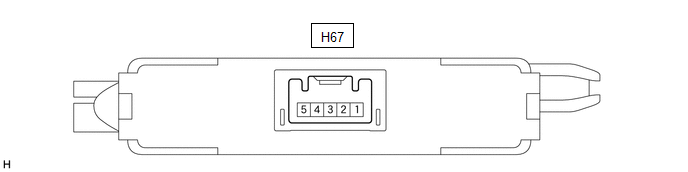
(a) Disconnect the H67 ID code box (immobiliser code ECU) connector.
(b) Measure the voltage and resistance according to the value(s) in the table below.
HINT:
Measure the values on the wire harness side with the connector disconnected.
| Terminal No. (Symbol) | Terminal Description | Switch Condition | Specified Condition |
|---|---|---|---|
| H67-1 (+B) - Body ground | Auxiliary battery power supply | Ignition switch off | 11 to 14 V |
| H67-5 (GND) - Body ground | Ground | Always | Below 1 Ω |
(c) Reconnect the H67 ID code box (immobiliser code ECU) connector.
(d) Check for pulses according to the value(s) in the table below.
| Terminal No. (Symbol) | Terminal Description | Switch Condition | Specified Condition |
|---|---|---|---|
| H67-2 (LIN1) - Body ground | LIN communication line | Ignition switch ON | Pulse generation |
 How To Proceed With Troubleshooting
CAUTION / NOTICE / HINT HINT:
Use the following procedure to troubleshoot the LIN communication system.
*: Use the GTS.
PROCEDURE 1. VEHICLE BROUGHT TO WORKSHOP
NEXT
2...
 Diagnosis System
DIAGNOSIS SYSTEM DESCRIPTION The main body ECU (multiplex network body ECU) and certification ECU (smart key ECU assembly) control the LIN communication system...
Other information:
Toyota Yaris XP210 (2020-2026) Reapir and Service Manual: System Description
SYSTEM DESCRIPTION CXPI COMMUNICATION SYSTEM DESCRIPTION The multiplex communication system [CXPI] is used for communication systems between body system components. When communication fails due to an open circuit, etc. on the communication line, the function that outputs a DTC related to the circuit according to the control master ECU and the fail-safe function that maintains minimum performance and protects the system activate...
Toyota Yaris XP210 (2020-2026) Reapir and Service Manual: Adjustment
ADJUSTMENT PROCEDURE 1. INSPECT AND ADJUST BRAKE PEDAL HEIGHT (a) Remove front door scuff plate LH. Click here (b) Remove cowl side trim board LH. Click here (c) Turn back floor carpet. (d) Turn back dash panel insulator assembly. (e) Check the brake pedal height...
Categories
- Manuals Home
- Toyota Yaris Owners Manual
- Toyota Yaris Service Manual
- Engine & Hybrid System
- Immobilizer System
- Brake System Control Module "A" System Voltage System Voltage Low (C137BA2)
- New on site
- Most important about car
Key Suspend Function
If a key is left in the vehicle, the functions of the key left in the vehicle are temporarily suspended to prevent theft of the vehicle.
To restore the functions, press the unlock button on the functions-suspended key in the vehicle.