Toyota Yaris: Lane Tracing Assist System / System Diagram
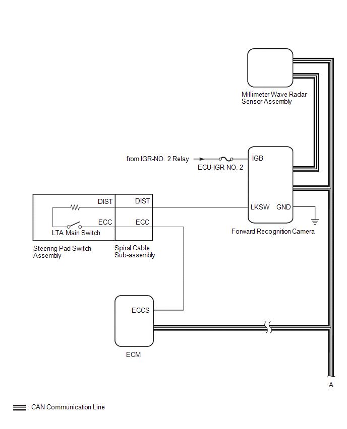
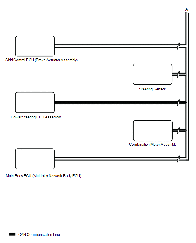
SYSTEM DIAGRAM
 Precaution
PRECAUTION NOTICE: If the auxiliary battery has been discharged and charged or the cable has been disconnected and reconnected to the negative (-) auxiliary battery terminal, perform Steering Sensor Zero Point Calibration...
 How To Proceed With Troubleshooting
CAUTION / NOTICE / HINT HINT:
Use the following procedure to troubleshoot the lane tracing assist system.
*: Use the GTS.
PROCEDURE 1. VEHICLE BROUGHT TO WORKSHOP
NEXT
2...
Other information:
Toyota Yaris XP210 (2020-2026) Owner's Manual: How to Use the Bluetooth® Audio System
Switching to Bluetooth® audio mode To listen to music or voice audio recorded to a Bluetooth® audio device, switch to the Bluetooth® audio mode to operate the audio device using the audio system control panel. Any Bluetooth® audio device must be paired to the vehicle’s Bluetooth® unit before it can be used...
Toyota Yaris XP210 (2020-2026) Reapir and Service Manual: Evaporator Temperature Sensor Circuit Short to Battery or Open (P053515)
DESCRIPTION The No. 1 cooler thermistor is installed to the evaporator in the air conditioner unit to detect the temperature of the cooled air that has passed through the evaporator, which is used to control the air conditioning system. It sends signals to the air conditioning amplifier assembly...
Categories
- Manuals Home
- Toyota Yaris Owners Manual
- Toyota Yaris Service Manual
- Key Battery Replacement
- G16e-gts (engine Mechanical)
- Fuel Gauge
- New on site
- Most important about car
Fuel Gauge
The fuel gauge shows approximately how much fuel is remaining in the tank when the ignition is switched ON. We recommend keeping the tank over 1/4 full.

Copyright © 2026 www.toyaris4.com