Toyota Yaris: Smart Key System (for Entry Function) / System Diagram
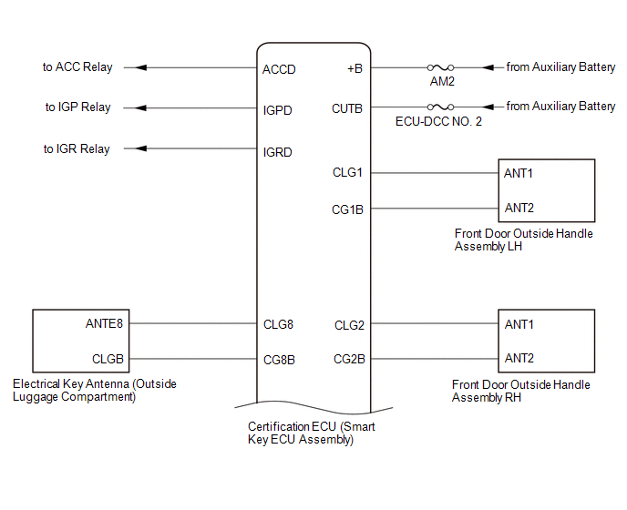
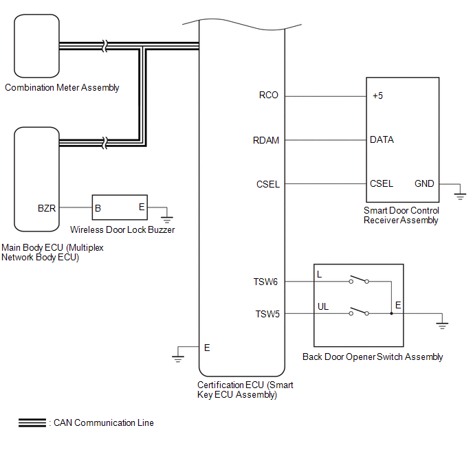
SYSTEM DIAGRAM
SMART KEY SYSTEM (for Entry Function)
SMART KEY SYSTEM (for Start Function)
Click here

POWER DOOR LOCK CONTROL SYSTEM
Click here

WIRELESS DOOR LOCK CONTROL SYSTEM
Click here

 How To Proceed With Troubleshooting
CAUTION / NOTICE / HINT HINT:
Replace parts related to the wireless door lock and smart key system according to the inspection procedure.
If the wireless door lock and smart key system does not operate, first check the customize item and make sure that the wireless door lock and smart key system is not turned off...
 Operation Check
OPERATION CHECK CHECK CUSTOMIZE PARAMETERS NOTICE: The operation check below is based on the non-customized initial condition of the vehicle. Click here
CHECK THE ENTRY UNLOCK FUNCTION (a) Check the entry unlock function (driver door, front passenger door)...
Other information:
Toyota Yaris XP210 (2020-2026) Owner's Manual: Key Battery Replacement
If the buttons on the smart key are inoperable and the operation indicator light does not flash, the battery may be dead. Replace with a new battery before the smart key becomes unusable. The following conditions indicate that the battery power is low: The KEY indicator light (green) flashes in the combination meter for about 30 seconds after the engine is switched OFF...
Toyota Yaris XP210 (2020-2026) Reapir and Service Manual: Lost Communication with ECM/PCM "A" Missing Message (U010087,U010487,U012287)
DESCRIPTION The ECM communicates with each sensor and ECU via CAN communication. If any malfunction is detected in a CAN communication circuit, one or more CAN communication system DTCs are stored. DTC No. Detection Item DTC Detection Condition Trouble Area DTC Output from U010087 Lost Communication with ECM/PCM "A" Missing Message When the dynamic radar cruise control system is operating, a communication malfunction between the skid control ECU (brake actuator assembly) and ECM is detected for approximately 1 second or more...
Categories
- Manuals Home
- Toyota Yaris Owners Manual
- Toyota Yaris Service Manual
- Immobilizer System
- Fuse Panel Description
- Brake System Control Module "A" System Voltage System Voltage Low (C137BA2)
- New on site
- Most important about car
Fuel Gauge
The fuel gauge shows approximately how much fuel is remaining in the tank when the ignition is switched ON. We recommend keeping the tank over 1/4 full.

Copyright © 2026 www.toyaris4.com