
Toyota Yaris: Heated Steering Wheel System / System Diagram
SYSTEM DIAGRAM
SYSTEM DIAGRAM

 Parts Location
PARTS LOCATION ILLUSTRATION
*1 SPIRAL CABLE SUB-ASSEMBLY *2 STEERING HEATER SWITCH *3 STEERING WHEEL ASSEMBLY - STEERING WHEEL HEATER UNIT - - ILLUSTRATION
*1 NO...
 System Description
SYSTEM DESCRIPTION HEATED STEERING WHEEL SYSTEM (a) The steering heater warms up the steering wheel when the steering heater switch is turned on. (b) The steering heater uses a control thermostat inside the steering wheel to maintain the steering wheel at the specified temperature...
Other information:
Toyota Yaris XP210 (2020-2026) Reapir and Service Manual: Components
COMPONENTS ILLUSTRATION *1 NO. 2 HEATER TO REGISTER DUCT SUB-ASSEMBLY *2 PACKAGE TRAY TRIM PANEL ASSEMBLY *3 DECK BOARD ASSEMBLY *4 DECK FLOOR BOX RH *5 DECK FLOOR BOX LH *6 FRONT DOOR OPENING TRIM WEATHERSTRIP LH *7 FRONT DOOR OPENING TRIM WEATHERSTRIP RH - - ILLUSTRATION *1 LAP BELT OUTER ANCHOR COVER *2 FRONT SEAT OUTER BELT ASSEMBLY LH *3 FRONT SEAT OUTER BELT ASSEMBLY RH *4 REAR SEATBACK HINGE SUB-ASSEMBLY LH *5 REAR SEATBACK HINGE SUB-ASSEMBLY RH *6 QUARTER TRIM PANEL ASSEMBLY LH *7 QUARTER TRIM PANEL ASSEMBLY RH *8 CENTER PILLAR UPPER GARNISH LH *9 CENTER PILLAR UPPER GARNISH RH *10 DECK TRIM REAR COVER *11 DECK TRIM SIDE PANEL ASSEMBLY LH *12 DECK TRIM SIDE PANEL ASSEMBLY RH *13 REAR SEAT OUTER BELT ASSEMBLY LH *14 REAR SEAT OUTER BELT ASSEMBLY RH *15 INNER ROOF SIDE GARNISH LH *16 INNER ROOF SIDE GARNISH RH *17 ROOF SIDE INNER GARNISH LH *18 ROOF SIDE INNER GARNISH RH *19 NO...
Toyota Yaris XP210 (2020-2026) Reapir and Service Manual: Brake Switch "A"/"B" Signal Cross Coupled (P05042B)
DESCRIPTION The stop light switch assembly is a duplex system that transmits two signals: STP and ST1-. These two signals are used by the ECM to monitor whether or not the brake system is working properly. If the signals, which indicate the brake pedal is being depressed and released, are detected simultaneously, the ECM interprets this as a malfunction in the stop light switch assembly and stores this DTC...
Categories
- Manuals Home
- Toyota Yaris Owners Manual
- Toyota Yaris Service Manual
- How to connect USB port/Auxiliary jack
- Brake System Control Module "A" System Voltage System Voltage Low (C137BA2)
- Engine & Hybrid System
- New on site
- Most important about car
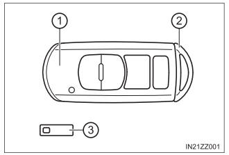
Keys
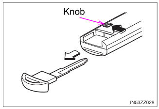
To use the auxiliary key, press the knob and pull out the auxiliary key from the smart key.

Copyright © 2026 www.toyaris4.com