Toyota Yaris: Monolithic Converter / Removal
REMOVAL
CAUTION / NOTICE / HINT
The necessary procedures (adjustment, calibration, initialization or registration) that must be performed after parts are removed and installed, or replaced during exhaust manifold converter sub-assembly removal/installation are shown below.
Necessary Procedures After Parts Removed/Installed/Replaced| Replaced Part or Performed Procedure | Necessary Procedure | Effect/Inoperative Function when Necessary Procedure not Performed | Link |
|---|---|---|---|
| Gas leaks from exhaust system is repaired | Inspection after repair |
|
|

CAUTION:
-
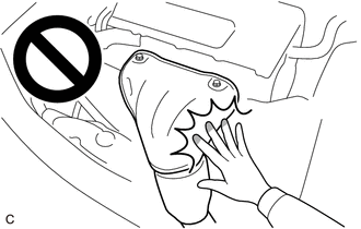
To prevent burns, do not touch the engine, exhaust manifold or other high temperature components while the engine is hot.
-
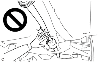
To prevent burns, do not touch the engine, exhaust pipe or other high temperature components while the engine is hot.
PROCEDURE
1. REMOVE AIR FUEL RATIO SENSOR
Click here

2. REMOVE PROPELLER SHAFT WITH CENTER BEARING ASSEMBLY
Click here

3. REMOVE FRONT SUSPENSION CROSSMEMBER SUB-ASSEMBLY
Click here

4. REMOVE EXHAUST MANIFOLD CONVERTER SUB-ASSEMBLY
CAUTION:
To prevent burns, do not touch the engine, exhaust manifold or other high temperature components while the engine is hot.
| (a) Remove the nut. |
|
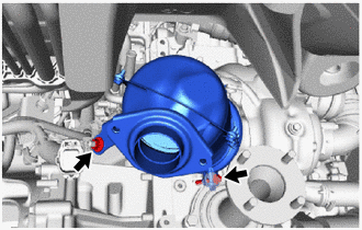
(b) Loosen the bolt and slide the exhaust pipe clamp and remove the exhaust manifold converter sub-assembly from the turbocharger sub-assembly.
| (c) Remove the exhaust pipe clamp from the exhaust manifold converter sub-assembly. |
|
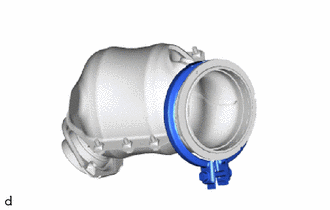
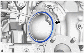
5. REMOVE OUTLET TURBINE ELBOW GASKET
| (a) Remove the outlet turbine elbow gasket from the turbocharger sub-assembly. |
|
 Components
COMPONENTS ILLUSTRATION
*1 EXHAUST MANIFOLD CONVERTER SUB-ASSEMBLY *2 EXHAUST PIPE CLAMP *3 OUTLET TURBINE ELBOW GASKET - -
N*m (kgf*cm, ft...
 Installation
INSTALLATION PROCEDURE 1. INSTALL TURBINE OUTLET ELBOW GASKET (a) Install a new outlet turbine elbow gasket to the turbocharger sub-assembly. 2. REPLACE EXHAUST MANIFOLD CONVERTER SUB-ASSEMBLY (a) Temporary install a new exhaust pipe clamp to the exhaust manifold converter sub-assembly...
Other information:
Toyota Yaris XP210 (2020-2026) Reapir and Service Manual: Headup Display Communication Stop Mode
DESCRIPTION Detection Item Symptom Trouble Area Headup Display Communication Stop Mode Communication stop for "Head Up Display" is indicated on the "Communication Bus Check" screen of the GTS. Click here Meter mirror sub-assembly branch line or connector Power source circuit of meter mirror sub-assembly Meter mirror sub-assembly ground circuit Meter mirror sub-assembly WIRING DIAGRAM CAUTION / NOTICE / HINT CAUTION: When performing the confirmation driving pattern, obey all speed limits and traffic laws...
Toyota Yaris XP210 (2020-2026) Owner's Manual: How to Use Aha™
Aha* 1 is an application which can be used to enjoy various Internet content such as Internet radio and podcasts. Stay connected to your friends activities by getting updates from Facebook and Twitter. Using the location-based service, nearby services and destinations can be searched or real-time local information can be obtained...
Categories
- Manuals Home
- Toyota Yaris Owners Manual
- Toyota Yaris Service Manual
- Maintenance
- Adjustment
- Diagnostic Trouble Code Chart
- New on site
- Most important about car
Liftgate/Trunk Lid
WARNING
Never allow a person to ride in the luggage compartment/trunk
Allowing a person to ride in the luggage compartment/trunk is dangerous. The person in the luggage compartment/trunk could be seriously injured or killed during sudden braking or a collision.
Do not drive with the liftgate/trunk lid open