Toyota Yaris: Roof Antenna / Removal
REMOVAL
CAUTION / NOTICE / HINT
HINT:
When the cable is disconnected / reconnected to the auxiliary battery terminal, systems temporarily stop operating. However, each system has a function that completes learning the first time the system is used.
-
Learning completes when vehicle is driven
Effect/Inoperative Function When Necessary Procedures are not Performed
Necessary Procedures
Link
Lane tracing assist system
Drive the vehicle straight ahead at 35 km/h (22 mph) or more for 5 second or more.

Pre-collision system
Stop and start system
Drive the vehicle until stop and start control is permitted (approximately 5 to 60 minutes)

-
Learning completes when vehicle is operated normally
Effect/Inoperative Function When Necessary Procedures are not Performed
Necessary Procedures
Link
Power door lock control system
- Back door opener
Perform door unlock operation with door control switch or electrical key transmitter sub-assembly switch.

Air conditioning system
After the ignition switch is turned to ON, the servo motor standard position is recognized.
-
PROCEDURE
1. REMOVE ROOF HEADLINING ASSEMBLY
Click here

2. REMOVE ROOF ANTENNA ASSEMBLY
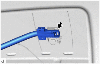
| (a) Disconnect the connector. |
|
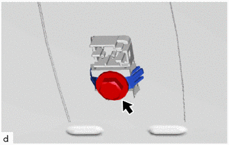
| (b) Remove the bolt and holder. |
|
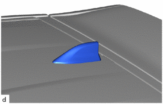
| (c) Remove the roof antenna assembly with antenna cover. |
|
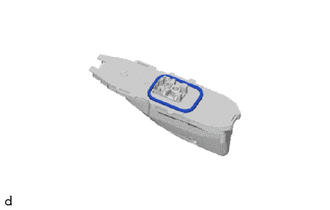
(d) Disengage the claws and guides to remove the roof antenna assembly from the antenna cover as shown in the illustration.
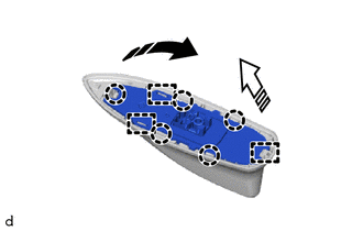
 | Remove in this Direction (1) |
 | Remove in this Direction (2) |
(e) When reusing the roof antenna assembly:
| (1) Remove the seal. |
|
 Components
COMPONENTS ILLUSTRATION
*1 ROOF ANTENNA ASSEMBLY *2 ANTENNA COVER *3 SEAL *4 HOLDER *5 ROOF ANTENNA HOUSING - -
N*m (kgf*cm, ft...
 Installation
INSTALLATION PROCEDURE 1. INSTALL ROOF ANTENNA ASSEMBLY (a) When reusing the roof antenna assembly: (1) Install a new seal.
(b) Engage the guides and claws to install the roof antenna assembly to the antenna cover as shown in the illustration...
Other information:
Toyota Yaris XP210 (2020-2026) Reapir and Service Manual: Dtc Check / Clear
DTC CHECK / CLEAR CHECK DTC (a) Check for DTCs (Test Failed / Pending / Confirmed). Powertrain > Radar Cruise1 > Trouble Codes Powertrain > Radar Cruise2 > Trouble Codes Radar Cruise1: Stored in the ECM Radar Cruise2: Stored in millimeter wave radar sensor assembly GTS Display Description Test Failed Represent malfunctions that were detected during the current trip...
Toyota Yaris XP210 (2020-2026) Reapir and Service Manual: Components
COMPONENTS ILLUSTRATION *1 REAR SHOCK ABSORBER ASSEMBLY *2 REAR STABILIZER LINK ASSEMBLY *3 REAR UPPER CONTROL ARM ASSEMBLY *4 REAR STABILIZER BAR *5 CAP - - Tightening torque for "Major areas involving basic vehicle performance such as moving/turning/stopping" : N*m (kgf*cm, ft...
Categories
- Manuals Home
- Toyota Yaris Owners Manual
- Toyota Yaris Service Manual
- How to use USB mode
- Maintenance
- Power Integration No.1 System Missing Message (B235287,B235587,B235787-B235987)
- New on site
- Most important about car
Key Suspend Function
If a key is left in the vehicle, the functions of the key left in the vehicle are temporarily suspended to prevent theft of the vehicle.
To restore the functions, press the unlock button on the functions-suspended key in the vehicle.