Toyota Yaris: Windshield Glass / Removal
REMOVAL
CAUTION / NOTICE / HINT
The necessary procedures (adjustment, calibration, initialization or registration) that must be performed after parts are removed and installed, or replaced during the windshield glass removal/installation are shown below.
Necessary Procedure After Parts Removed/Installed/Replaced| Replacement Part | Necessary Procedure | Effect/Inoperative Function when Necessary Procedures are not Performed | Link |
|---|---|---|---|
| Windshield glass (Including removal and installation) | Adjust forward recognition camera |
| One Time Recognition:
Sequential Recognition:
Driving Adjustment:
|
NOTICE:
- When replacing the windshield glass of a vehicle equipped with a forward recognition camera, make sure to use a Toyota genuine part. If a non-Toyota genuine part is used, the forward recognition camera may not be able to be installed due to a missing bracket. Also, the dynamic radar cruise control system, lane tracing assist system, pre-collision system, front camera system or auto high beam system may not operate properly due to a difference in the transmissivity or black ceramic border.
- Make sure to use Toyota Genuine Windshield Glass Adhesive (High Modulus Type) or equivalent.
PROCEDURE
1. REMOVE WINDSHIELD WIPER MOTOR AND LINK
Click here
.gif)
2. REMOVE FORWARD RECOGNITION WITH HEATER HOOD SUB-ASSEMBLY (w/ Pre-collision System)
Click here
3. REMOVE RAIN SENSOR
Click here
4. REMOVE INNER REAR VIEW MIRROR ASSEMBLY
Click here
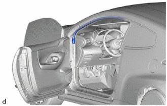
5. SEPARATE FRONT DOOR OPENING TRIM WEATHERSTRIP LH
| (a) Separate the front door opening trim weatherstrip LH. |
|
6. SEPARATE FRONT DOOR OPENING TRIM WEATHERSTRIP RH
HINT:
Use the same procedure as for the LH side.
7. REMOVE FRONT PILLAR GARNISH LH
Click here
8. REMOVE FRONT PILLAR GARNISH RH
HINT:
Use the same procedure as for the LH side.
9. REMOVE MAP LIGHT ASSEMBLY
Click here
10. REMOVE VISOR ASSEMBLY LH
Click here
11. REMOVE VISOR ASSEMBLY RH
HINT:
Use the same procedure as for the LH side.
12. REMOVE VISOR HOLDER LH
Click here
13. REMOVE VISOR HOLDER RH
HINT:
Use the same procedure as for the LH side.
14. REMOVE ASSIST GRIP COVER
Click here
15. REMOVE ASSIST GRIP SUB-ASSEMBLY
Click here
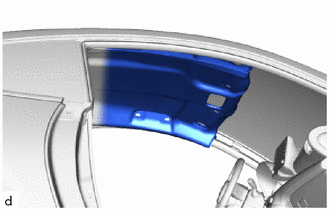
16. SEPARATE ROOF HEADLINING
| (a) Slightly lower the front section of the roof headlining so that the windshield glass can be removed. NOTICE: Do not damage the roof headlining or vehicle interior. HINT: It is not necessary to completely remove the roof headlining. |
|
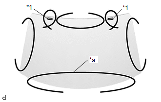
17. REMOVE WINDSHIELD GLASS
(a) Apply protective tape to the area around the installation position of the windshield glass on the vehicle body to prevent it from being scratched.
.png) | Protective Tape |
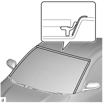
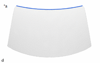
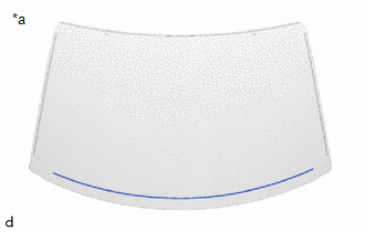
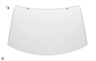
(b) When reusing the windshield glass:
| (1) Place matchmarks on the windshield glass and vehicle body at the locations indicated in the illustration. |
|
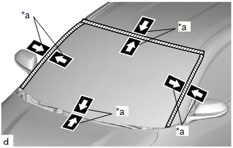
| (c) Pass a piano wire between the vehicle body and windshield glass from the interior. |
|
(d) Tie both wire ends to wooden blocks or similar objects that can serve as handles.
(e) Cut the adhesive by pulling the piano wire around the windshield glass.
NOTICE:
- When separating the windshield glass, be careful not to damage the paint or interior and exterior ornaments.
- To prevent the instrument panel safety pad sub-assembly from being scratched when removing the windshield glass, place a plastic sheet between the piano wire and instrument panel safety pad sub-assembly.
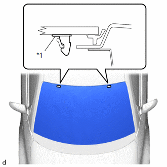
| (f) Disengage the windshield glass stoppers. NOTICE:
|
|
(g) Using suction cups, remove the windshield glass.
NOTICE:
- Be careful not to drop the windshield glass.
- Leave as much adhesive on the vehicle body as possible when removing the windshield glass.
18. REMOVE WINDSHIELD OUTSIDE MOULDING
(a) When reusing the windshield glass:
| (1) Using a scraper, remove the windshield outside moulding. NOTICE:
|
|
19. REMOVE NO. 2 WINDOW GLASS ADHESIVE DAM
(a) When reusing the windshield glass:
| (1) Using a scraper, remove the No. 2 window glass adhesive dam. NOTICE:
|
|
20. REMOVE WINDOW GLASS ADHESIVE DAM
(a) When reusing the windshield glass:
| (1) Using a scraper, remove the 2 window glass adhesive dams. NOTICE:
|
|

21. REMOVE WINDSHIELD GLASS STOPPER
(a) When reusing the windshield glass:
| (1) Using a scraper, remove the 2 windshield glass stoppers. NOTICE:
|
|
 Components
COMPONENTS ILLUSTRATION
*1 FRONT DOOR OPENING TRIM WEATHERSTRIP LH *2 FRONT DOOR OPENING TRIM WEATHERSTRIP RH *3 FRONT PILLAR GARNISH LH *4 FRONT PILLAR GARNISH RH *5 FRONT PILLAR GARNISH CLIP - - ● Non-reusable part - - ILLUSTRATION
*A w/ Pre-collision System - - *1 VISOR ASSEMBLY LH *2 VISOR ASSEMBLY RH *3 VISOR HOLDER LH *4 VISOR HOLDER RH *5 ASSIST GRIP COVER *6 ASSIST GRIP SUB-ASSEMBLY *7 ROOF HEADLINING *8 FORWARD RECOGNITION WITH HEATER HOOD SUB-ASSEMBLY ILLUSTRATION
*1 WINDSHIELD GLASS *2 WINDSHIELD OUTSIDE MOULDING *3 NO...
 Installation
INSTALLATION CAUTION / NOTICE / HINT NOTICE:
When replacing the windshield glass of a vehicle equipped with a forward recognition camera, make sure to use a Toyota genuine part...
Other information:
Toyota Yaris XP210 (2020-2026) Reapir and Service Manual: Throttle Actuator "A" Control System Actuator Stuck Open (P211172,P211173)
DESCRIPTION The throttle actuator is operated by the ECM, and opens and closes the throttle valve using gears. The opening angle of the throttle valve is detected by the throttle position sensor, which is mounted on the throttle body with motor assembly...
Toyota Yaris XP210 (2020-2026) Owner's Manual: Center Console Tray
A cup or small items can be placed on the center console tray using the center console divider. The center console tray is large enough to place a small item when the center console divider is not in use. WARNING Never use a cup holder to hold hot liquids while the vehicle is moving Using a cup holder to hold hot liquids while the vehicle is moving is dangerous...
Categories
- Manuals Home
- Toyota Yaris Owners Manual
- Toyota Yaris Service Manual
- How to connect USB port/Auxiliary jack
- G16e-gts (engine Mechanical)
- Brake System Control Module "A" System Voltage System Voltage Low (C137BA2)
- New on site
- Most important about car
Front Seat Belt Pretensioners
The front seat belt pretensioners are designed to deploy in moderate or severe frontal, near frontal collisions.
In addition, the pretensioners operate when a side collision or a rollover accident is detected. The pretensioners operate differently depending on what types of air bags are equipped. For more details about the seat belt pretensioner operation, refer to the SRS Air Bag Deployment Criteria.