Toyota Yaris: Rear Suspension Member / Removal
REMOVAL
CAUTION / NOTICE / HINT
The necessary procedures (adjustment, calibration, initialization, or registration) that must be performed after parts are removed and installed, or replaced during rear suspension member sub-assembly removal/installation are shown below.
Necessary Procedures After Parts Removed/Installed/Replaced| Replaced Part or Performed Procedure | Necessary Procedure | Effect/Inoperative Function when Necessary Procedure not Performed | Link |
|---|---|---|---|
| Rear wheel alignment adjustment | ECU Data Initialization | Active torque split AWD system |
|
| Calibration |
|
|


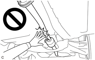
CAUTION:
To prevent burns, do not touch the engine, exhaust pipe or other high temperature components while the engine is hot.
PROCEDURE
1. REMOVE REAR DIFFERENTIAL CARRIER ASSEMBLY
Click here

2. REMOVE REAR STABILIZER BAR
Click here

3. REMOVE REAR SUSPENSION MEMBER SUB-ASSEMBLY
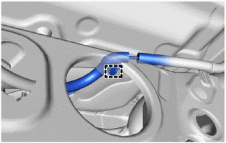
| (a) Disengage the clamp to separate the differential carrier wire harness. |
|
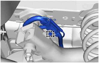
| (b) Disengage the clamp to separate the differential carrier wire harness. |
|
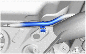
| (c) Disengage the clamp to separate the differential carrier wire harness. |
|
(d) Using an engine lifter and 4 attachments or equivalent tools, support the rear suspension member sub-assembly as shown in the illustration.
CAUTION:
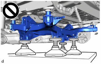
- The rear suspension member sub-assembly is a very heavy component. Make sure that it is supported securely.
- If the rear suspension member sub-assembly is not securely supported, it may drop, resulting in serious injury.
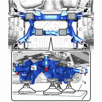
| *a | Engine Lifter |
| *b | Attachment |
 | Attachment and Wooden Block Placement Location |
NOTICE:
Use attachments and wooden blocks to keep the rear suspension member sub-assembly level.
(e) Remove the 2 bolts and 2 nuts.
(f) Slowly lower the rear suspension member sub-assembly.
NOTICE:
When lowering the rear suspension member sub-assembly, be careful not to damage the vehicle body or other components installed to the vehicle.
4. REMOVE REAR UPPER CONTROL ARM ASSEMBLY LH
Click here

5. REMOVE REAR UPPER CONTROL ARM ASSEMBLY RH
HINT:
Perform the same procedure as for the LH side.
6. REMOVE REAR NO. 1 DIFFERENTIAL MOUNT CUSHION
Click here

7. REMOVE REAR SUSPENSION MEMBER HOLE COVER
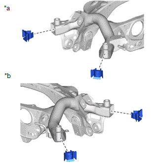
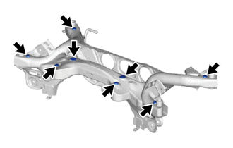
| (a) Remove the 4 rear suspension member hole covers from the rear suspension member sub-assembly as shown in the illustration. |
|
8. REMOVE HOLE PLUG
| (a) Remove the 8 hole plugs from the rear suspension member sub-assembly as shown in the illustration. |
|
 Components
COMPONENTS ILLUSTRATION
*1 REAR STABILIZER BAR *2 REAR SUSPENSION MEMBER SUB-ASSEMBLY *3 REAR UPPER CONTROL ARM ASSEMBLY LH *4 REAR UPPER CONTROL ARM ASSEMBLY RH
Tightening torque for "Major areas involving basic vehicle performance such as moving/turning/stopping" : N*m (kgf*cm, ft...
 Installation
INSTALLATION PROCEDURE 1. INSTALL HOLE PLUG (a) Install the 8 hole plugs to the rear suspension member sub-assembly. 2. INSTALL REAR SUSPENSION MEMBER HOLE COVER (a) Install the 4 rear suspension member hole covers to the rear suspension member sub-assembly...
Other information:
Toyota Yaris XP210 (2020-2026) Reapir and Service Manual: Throttle Actuator "A" Control Throttle Body Range/Performance (P211900,P211904,P211977,P21199B)
DESCRIPTION The electronic throttle control system is composed of the throttle actuator, throttle position sensor, accelerator pedal position sensor, and ECM. The ECM operates the throttle actuator to regulate the throttle valve in response to driver inputs...
Toyota Yaris XP210 (2020-2026) Reapir and Service Manual: Engine Oil Pressure Too Low (P052400)
DESCRIPTION Refer to DTC P052012 DTC No. Detection Item DTC Detection Condition Trouble Area MIL Note P052400 Engine Oil Pressure Too Low When the engine is running, the oil pressure value output from the engine oil pressure and temperature sensor is less than the target value (1 trip detection logic)...
Categories
- Manuals Home
- Toyota Yaris Owners Manual
- Toyota Yaris Service Manual
- Removal
- G16e-gts (engine Mechanical)
- Opening and Closing the Liftgate/Trunk Lid
- New on site
- Most important about car
Keys
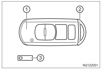
To use the auxiliary key, press the knob and pull out the auxiliary key from the smart key.