Toyota Yaris: Integration Relay / Removal
REMOVAL
CAUTION / NOTICE / HINT
HINT:
When the cable is disconnected / reconnected to the auxiliary battery terminal, systems temporarily stop operating. However, each system has a function that completes learning the first time the system is used.
-
Learning completes when vehicle is driven
Effect/Inoperative Function When Necessary Procedures are not Performed
Necessary Procedures
Link
Lane tracing assist system
Drive the vehicle straight ahead at 35 km/h (22 mph) or more for 5 second or more.

Pre-collision system
Stop and start system
Drive the vehicle until stop and start control is permitted (approximately 5 to 60 minutes)

-
Learning completes when vehicle is operated normally
Effect/Inoperative Function When Necessary Procedures are not Performed
Necessary Procedures
Link
Power door lock control system
- Back door opener
Perform door unlock operation with door control switch or electrical key transmitter sub-assembly switch.

Air conditioning system
After the ignition switch is turned to ON, the servo motor standard position is recognized.
-
PROCEDURE
1. PRECAUTION
NOTICE:
After turning the ignition switch off, waiting time may be required before disconnecting the cable from the negative (-) auxiliary battery terminal.
Click here

2. DISCONNECT CABLE FROM NEGATIVE AUXILIARY BATTERY TERMINAL
Click here

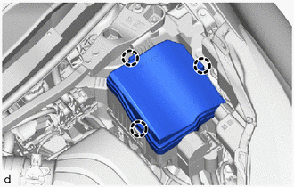
3. REMOVE NO. 1 RELAY BLOCK COVER
| (a) Disengage the claws to remove the No. 1 relay block cover. |
|
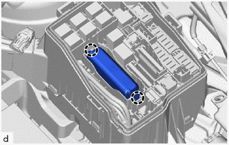
4. REMOVE SEMICONDUCTOR POWER INTEGRATION ECU
NOTICE:
- Make sure the connector terminal is free from oil and grease.
- Do not subject the semiconductor power integration ECU to any impact.
- Do not use a semiconductor power integration ECU that has been dropped.
- Do not disassemble the semiconductor power integration ECU.
| (a) Disengage the claws and pull up the semiconductor power integration ECU. |
|
| (b) Disconnect the power source connector. |
|
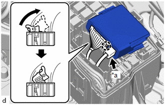
(c) Disengage the claw and pull up the lock lever to disconnect the connector as shown in the illustration.
 Components
C..
 Installation
INSTALLATION PROCEDURE 1. INSTALL SEMICONDUCTOR POWER INTEGRATION ECU NOTICE:
Make sure the connector terminal is free from oil and grease.
Do not subject the semiconductor power integration ECU to any impact...
Other information:
Toyota Yaris XP210 (2020-2026) Reapir and Service Manual: Light Sensor Circuit Malfunction (B124400)
DESCRIPTION The automatic light control sensor detects ambient light. The sensor creates an electrical signal based on the amount of light detected, and sends the signal to the main body ECU (multiplex network body ECU). The main body ECU (multiplex network body ECU) turns on or off the headlights and taillights according to the signal...
Toyota Yaris XP210 (2020-2026) Reapir and Service Manual: On-vehicle Inspection
ON-VEHICLE INSPECTION PROCEDURE 1. INSPECT STOP LIGHT SWITCH ASSEMBLY (a) Disconnect the stop light switch assembly connector. (b) Measure the voltage and resistance on the wire harness side connector according to the value(s) in the table below. Standard Voltage: Tester Connection Condition Specified Condition A63-7 (B) - A63-2 (GND) Always 11 to 14 V A63-6 (B) - A63-2 (GND) Ignition switch on (IG) 11 to 14 V Standard Resistance: Tester Connection Condition Specified Condition A63-2 (GND) - Body ground Always Below 1 Ω If the result is not as specified, repair or replace the wire harness or connector...
Categories
- Manuals Home
- Toyota Yaris Owners Manual
- Toyota Yaris Service Manual
- Immobilizer System
- Adjustment
- How to connect USB port/Auxiliary jack
- New on site
- Most important about car
Refueling
Before refueling, close all the doors, windows, and the liftgate/trunk lid, and switch the ignition OFF.
To open the fuel-filler lid, pull the remote fuel-filler lid release.
