Toyota Yaris: G16e-gts (starting) / Relay
Inspection
INSPECTION
PROCEDURE
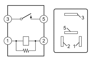
1. INSPECT ST NO. 1 RELAY
| (a) Check the resistance. (1) Measure the resistance according to the value(s) in the table below. Standard Resistance:
If the result is not as specified, replace the ST No. 1 relay. |
|
 Engine Switch
ComponentsCOMPONENTS ILLUSTRATION
*1 CENTER LOWER INSTRUMENT COVER *2 LOWER INSTRUMENT PANEL FINISH PANEL *3 ENGINE SWITCH - - RemovalREMOVAL PROCEDURE 1...
 Starter
..
Other information:
Toyota Yaris XP210 (2020-2026) Reapir and Service Manual: Precaution
PRECAUTION CAUTION: Replace any faulty parts of the seat belt systems (outer belt, inner belt, bolts, nuts, adjustable shoulder anchor, tether anchor hardware and other related parts). When inspecting a vehicle that has been involved in a collision, be sure to check all of the seat belt systems regardless of whether or not the system was activated in the collision...
Toyota Yaris XP210 (2020-2026) Reapir and Service Manual: Removal
REMOVAL CAUTION / NOTICE / HINT HINT: When the cable is disconnected/reconnected to the auxiliary battery terminal, systems temporarily stop operating. However, each system has a function that completes learning the first time the system is used. Learning completes when vehicle is driven Effect/Inoperative Function When Necessary Procedures are not Performed Necessary Procedures Link Lane tracing assist system Drive the vehicle straight ahead at 35 km/h (22 mph) or more for 5 second or more...
Categories
- Manuals Home
- Toyota Yaris Owners Manual
- Toyota Yaris Service Manual
- G16e-gts (engine Mechanical)
- Diagnostic Trouble Code Chart
- Immobilizer System
- New on site
- Most important about car
Refueling
Before refueling, close all the doors, windows, and the liftgate/trunk lid, and switch the ignition OFF.
To open the fuel-filler lid, pull the remote fuel-filler lid release.

Copyright © 2026 www.toyaris4.com